Do you have a question about the Mecmesin Tornado and is the answer not in the manual?
Check for physical damage to packaging, case, or instrument upon receiving the unit.
Commonly used features accessible via dedicated keys; advanced features use a menu system.
Care needed when cleaning the keypad to avoid liquid spillage onto the membrane.
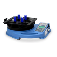
Steps to attach the top plate, including handle position and screw tightening for 6N.m and 10N.m models.
Top plate is removed during transit to prevent torque cell damage.
Steps to attach the top plate, including handle position and screw tightening for 1.5N.m/3N.m models with sensor warning.
Top plate is removed during transit to prevent torque cell damage.
Instructions for replacing the rechargeable batteries in the Tornado unit.
Describes the symbol that appears when the battery is low and the unit will power down.
Explains how to power the Tornado directly from the mains using the adaptor/charger.
How to use the 4 pegs to grip the sample securely during testing.
Instructions on how to power on the Tornado, including the self-test sequence.
How the Tornado displays torque direction and the load indicator bar.
Procedures for zeroing the display and changing measurement units.
Explains how to use Max mode, Dual Max, and specific peak readings.
Exiting Max mode to return to a running display and reset.
Describes the analogue output available from the 'D type' connector for external devices.
Details transmitting data via RS232 or Digimatic, including continuous transmission.
Details RS232 communication parameters like baud rate, data bits, parity, and flow control.
Explains how to navigate the Tornado's advanced menus using the function keys.
How to select and activate one of the five stored alarm settings.
Step-by-step guide to configure alarm parameters and activate them.
Defines and sets the upper and lower limits for the alarm triggers.
Selects how the pass/fail status is indicated (Audible, LED, or Both).
Chooses whether alarms trigger for values 'OUT BAND' or 'IN BAND'.
Defines what constitutes a 'PASS' or 'FAIL' based on the alarm band settings.
Configures the buzzer sound mode (Continuous or Pulse) for active alarms.
Sets the PLC signal output (OFF, AT LIMITS, AT ALARM) for external control.
Configures the output signal trigger for 'AT LIMITS' based on load limits.
Configures the PLC signal to be high or low based on Tornado's alarm status.
Enables or disables password protection for menu pages.
Configures the Tornado to freeze the display on specific external signals.
How to enable the tamper-evident testing feature.
Adjusts the percentage drop for calculating slip and bridge torques.
Selects which peaks (1st, 2nd, or both) are transmitted via TXD.
Lists and explains the different max display modes when % TAMP EV is enabled.
How to enable the function for calculating average load readings over time.
Defines the percentage thresholds for starting and stopping the averaging process.
Chooses between MEDIUM (80Hz) and HIGH (2000Hz) data capture rates.
Assigns one of the five main key functions (MAX, UNITS, TXD, ZERO, RESET) to Footswitch 1.
Assigns one of the five main key functions to Footswitch 2.
Sets up communication with peripheral devices, including unit transmission and BAUD rate.
Controls whether the unit of measurement is included in transmitted data.
Determines if a negative sign is transmitted for counter-clockwise readings.
Configures the Baud rate and terminal characters (NULL, CR, LF) for communication.
Sets a line delay and a transmission threshold percentage for data output.
Selects the method of transmission: RS232, Digimatic, or Dual.
Configures the device to store readings in internal memory by pressing the TXD key.
Transmits all stored load readings to a peripheral device.
Erases all stored data from the internal memory.
Provides methods to check the torque sensor's condition, especially after an overload.
Accesses the torque sensor diagnostic test screen for detailed information.
Prevents changes to the Max display mode by locking it.
Prevents changes to the selected unit of measurement by locking it.
Enables or disables the backlight for the Tornado display.
Sets the time for the Tornado to automatically power down to conserve battery.
Reverses the display orientation for easier reading in certain handle positions.
Restores the Tornado to its original factory default settings.
Table detailing RS232 commands for configuring and querying the Tornado.
Explains the responses to various RS232 commands like M, U, C, and @.
Details the meaning of specific parameters when various functions are enabled.
Visual guide to navigating the Alarm configuration sub-menus.
Visual guide to navigating the PLC integration sub-menus.
Visual guide to navigating the Password protection sub-menus.
Visual guide to navigating the Freeze display configuration sub-menus.
Visual guide to navigating the Tamper-Evident Testing sub-menus.
Visual guide to navigating the Average/Time calculation sub-menus.
Visual guide to navigating the Data Capture Rate sub-menus.
Visual guide to assigning functions to Footswitch 1.
Visual guide to assigning functions to Footswitch 2.
Visual guide to navigating the Communication settings sub-menus.
Visual guide to navigating the calibration and diagnostic sub-menus.
Visual guide to navigating the Max display lock sub-menus.
Visual guide to navigating the Units lock sub-menus.
Visual guide to navigating the Backlight control sub-menus.
Visual guide to navigating the Auto Power Off sub-menus.
Visual guide to navigating the Display Invert sub-menus.
Visual guide to navigating the Restore Factory Defaults sub-menus.
Shows the height and depth measurements of the Tornado from a side perspective.
Displays width, depth, and min-max opening ranges for different Tornado models.
Details the accuracy and resolution across various capacities and units.
Details output characteristics for RS232, Digimatic, Analogue, and PLC signals.
Information about the solid-state relay, its PCB, and connection cable.
Details supply voltage, input control, and output characteristics of the relay.
Specifies the IP54 water resistance rating and its conditions.
Information on the primary and secondary specifications of the supplied mains adaptor/charger.
Lists available interface cables and their corresponding Mecmesin part numbers.
Details the pin assignments for the 15-way 'D Type' communication connector.
| Brand | Mecmesin |
|---|---|
| Model | Tornado |
| Category | Test Equipment |
| Language | English |