CHARGING SYSTEM SERVICE MANUAL NUMBER 23
Page 4C-26 90-861326--1 MARCH 1999
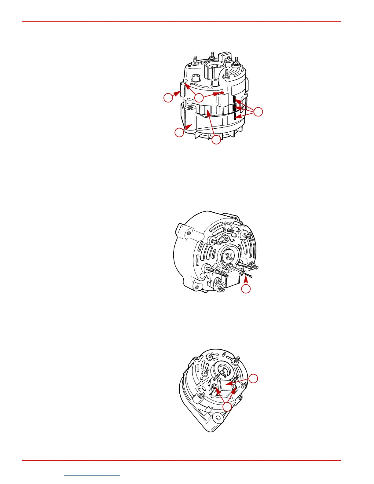
8. Position rear end frame and stator assembly over front end frame and rotor assembly
and align scribe marks on each (scribed during disassembly). Hand-press end frames
together, then install four screws. Tighten screws securely.
72561
d
a
b
c
e
a-Rear End Frame
b-Stator
c-Front End Frame
d-Scribe Marks
e-Insert Screws (4) (Two Hidden)
9. Depress brushes flush with top of brush holder and insert a #54,.050 in. drill bit or smaller
into hole in brush holder to hold brushes compressed during reassembly.
72836
a
a-Drill Bit
NOTE: Rubber gasket shown removed for clarity.
10. Install brush/regulator assembly in rear end frame cavity and secure with two mounting
screws, as shown. Tighten screws securely. Remove drill bit to release brushes against
slip rings.
72837
a
b
a-Brush / Regulator Assembly
b-Mounting Screws
Downloaded from https://needmanual.com/!
 Loading...


