WIRING DIAGRAMS
SERVICE MANUAL NUMBER 23
90-861326--1 MARCH 1999 Page 4E-17
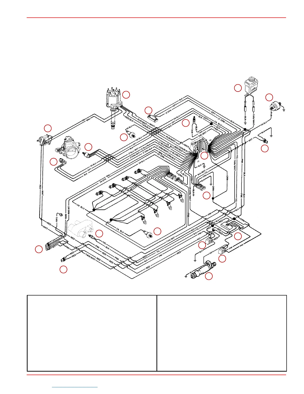
MEFI 3 MCM (Sterndrive) 7.4L MPI Bravo and MIE (Inboard) 7.4L Inboard
NOTE: All BLACK wires with a ground symbol are interconnected within the EFI system har-
ness.
NOTE: Component position and orientation shown is arranged for visual clarity and ease
of circuit identification.
75993
12
13
14
15
16
1
2
3
4
5
6
7
7
8
9
10
11
17
18
19
1-Fuel Pump
2-Distributor
3-Coil
4-Gear Lube Monitor Bottle (Not Used On MIE)
5-Data Link Connector (DLC)
6-Manifold Absolute Pressure (MAP) Sensor
7-Knock Sensor
8-Idle Air Control (IAC)
9-Throttle Position (TP) Sensor
10 - Engine Coolant Temperature (ECT) Sensor
11 - Electronic Control Module (ECM)
12 - Fuel Pump Relay
13 - Ignition/System Relay
14 - Fuse (15 Amp) Fuel Pump
Fuse (15 Amp) ECM / DLC / Battery
Fuse (10 Amp) ECM / Injector / Ignition /
Knock Module
15 - Harness Connector To Starting/Charging
Harness
16 - Positive (+) Power Wire To Engine Circuit
Breaker
17 - OIl Pressure - Audio Warning Switch
18 - Load Anticipation Circuit (Not Used On MCM)
19 - Manifold Air Temperature (MAT) Sensor
Downloaded from https://needmanual.com/!
 Loading...


