TROUBLE CODE DIAGNOSTICS - 7.4L MPI SERVICE MANUAL NUMBER 23
Page 5G-16 90-861326--1 MARCH 1999
Code 23 (2 of 3): Intake Air Temperature (IAT) Sensor Circuit (Non-Scan) Low
Temperature Indicated
INTAKE AIR TEMPERATURE SENSOR CHART
IAT Sensor
Temperature - to - Resistance Values (Approximate)
°F °C OHMS
210
160
100
70
40
20
0
-40
100
70
38
20
4
-7
-18
-40
185
450
1,800
3,400
7,500
13,500
25,000
100,700
Code 25 (1 of 3): Intake Air Temperature (IAT) Sensor Circuit (Non-Scan) High
Temperature Indicated
AB
a
b
c
d
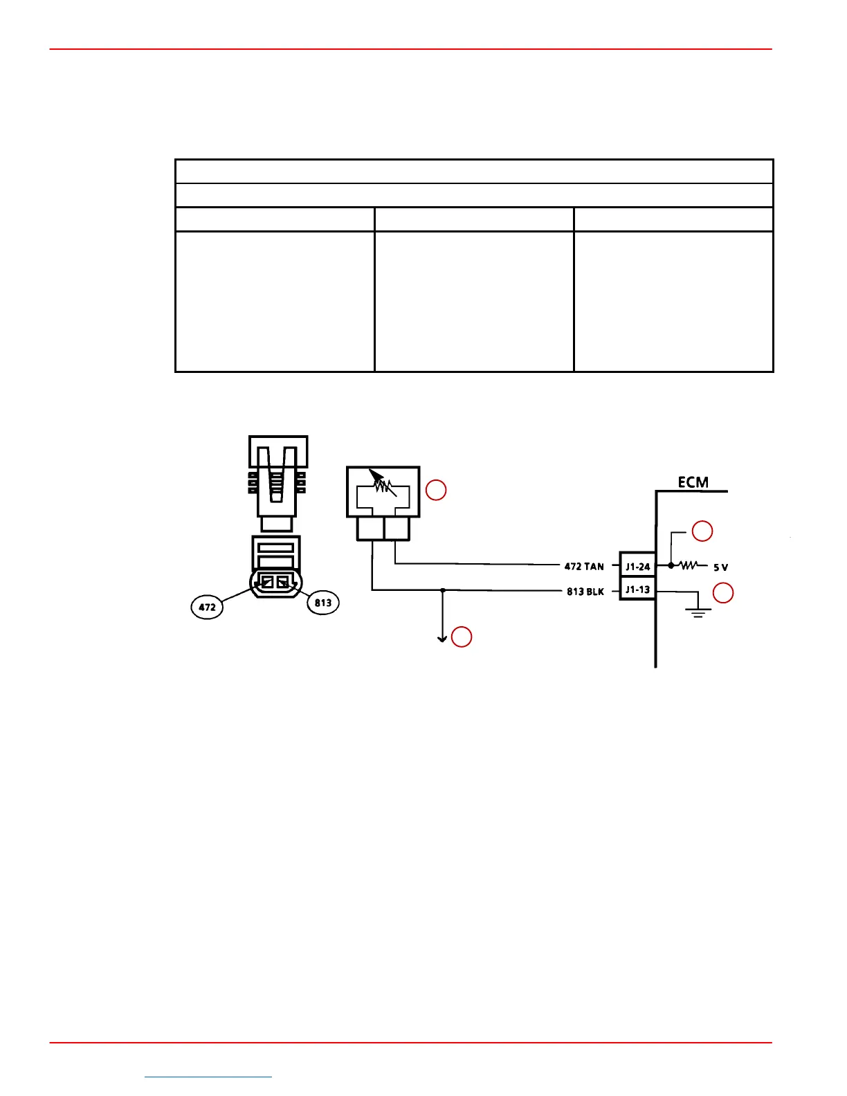
a-Intake Air Temperature Sensor
b-To TP Sensor
c-IAT Sensor Signal
d-Sensor Ground
CIRCUIT DESCRIPTION:
The Intake Air Temperature (IAT) sensor uses a thermistor to control the signal voltage to
the ECM. The ECM applies 5 volts on CKT 472 to the sensor. When the intake air is cold,
the sensor (thermistor) resistance is high. As the intake air warms up, the sensor resistance
becomes less. See intake air temperature sensor chart under “Diagnostic Aids.” At normal
operating temperature 160°F-180°F (71°C-82°C), the voltage will measure about 1.5-2.0
volts.
Downloaded from https://needmanual.com/!
 Loading...


