MULTI-PORT FUEL INJECTION DISASSEMBLY AND REASSEMBLY
SERVICE MANUAL NUMBER 23
90-861326--1 MARCH 1999 Page 5C-29
INSTALLATION
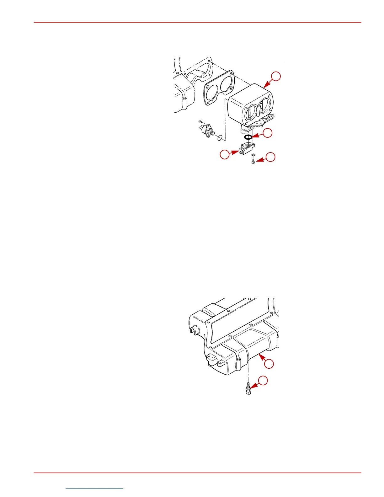
1. Install TP sensor on throttle body using screws with lock washers and Loctite 242 ap-
plied to threads. Torque screws to 20 lb. in (2 Nm).
72800
a
b
c
d
a-Throttle Body
b-Throttle Position (TP) Sensor
c-Screws With Lockwashers
d-O-Ring
2. Install throttle body, throttle cable and flame arrestor as outlined in “Throttle Body.”
3. When negative (–) battery cable has been reconnected, start engine and check the TP
sensor output voltage. It should be approximately .7 Volts at idle and 4.5 Volts at W.O.T.
Intake Air Temperature (IAT) Sensor
REMOVAL
1. Remove flame arrestor, throttle linkage, throttle body and plenum as outlined in
“Plenum.”
2. Remove IAT sensor from plenum.
72802
a
b
a-Plenum
b-Intake Air Temperature (IAT) Sensor
CLEANING AND INSPECTION
1. Clean the surfaces of the IAT sensor with a dry cloth.
2. Inspect the IAT sensor for signs of wear or damage.
Downloaded from https://needmanual.com/!
 Loading...


