20 BA 2076/02/01
7 Indication and Parameterization
Hy
st
er
es
is
S1
2,5
°C
Sav
e ?
YES
NO
De
la
y-
Ti
me
S1
2,0
s
_
Sav
e ?
YES
NO
Alternate S1
Alternate On
Alternate Off
Save ?
YES NO
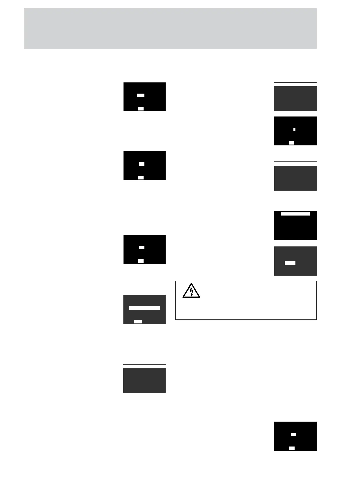
Setting the switching pointSetting the switching point
Setting the switching pointSetting the switching point
Setting the switching point
The temperature value can be set here at
which the switching contacts are to be
switched on.
The temperature value refers either to the
oil temperature or to the winding
temperature depending on the setting in the menu item
<Configuration>.
Setting the hysterSetting the hyster
Setting the hysterSetting the hyster
Setting the hyster
esisesis
esisesis
esis
The adjustable hysteresis always becomes
active when switching back (dropping
temperature). The respective relay is
switched when the switching point is
exceeded. Switch back takes place at the
value (switching point hysteresis).
The amount of hysteresis is set in this menu item. A minimum
hysteresis of 1% of the measuring range cannot be dropped
below.
Setting the delay timeSetting the delay time
Setting the delay timeSetting the delay time
Setting the delay time
The delay time can be used to provide a
time delay in the switching contact. If
the switching contact is not to be
switched until 30 seconds after the
switching point is reached, for example,
this value must be set in this menu item.
Assigning the switching contact to load change operAssigning the switching contact to load change oper
Assigning the switching contact to load change operAssigning the switching contact to load change oper
Assigning the switching contact to load change oper
ationation
ationation
ation
If the switching contact is added to the
load change circuit, <Alternate On> must
be set in this menu item. For more
information on the load change circuit,
see page 14 in chapter 5.7.
<Alternate Off> means that the switching contact is not
assigned to load change operation.
7.47.4
7.47.4
7.4
<MANUFACTURER> Menu<MANUFACTURER> Menu
<MANUFACTURER> Menu<MANUFACTURER> Menu
<MANUFACTURER> Menu
The following manufacturer-specific data
are stored under this menu.
• Device type
• Serial number
• Date of manufacture
• Input range of the sensor
• Software version
• Software date
<-MANUFACTURER->
Device Type_
Serial No.
Manufact. Date
Input Range_
Software Version
Software Date_
RS485 Adresse
RS4RS48585-A-Addddresress_
7_7_
SavSave ? e ?
YESYES NO NO
7.57.5
7.57.5
7.5
<OPERATOR> Menu<OPERATOR> Menu
<OPERATOR> Menu<OPERATOR> Menu
<OPERATOR> Menu
Information of the operator can be called
under this menu. Except for the setting of
the RS485 address, this information can
only be entered with the visualization
software.
The RS485 address is set with the <UP>
and <DOWN> keys and confirmed.
7.67.6
7.67.6
7.6
<USER> Menu<USER> Menu
<USER> Menu<USER> Menu
<USER> Menu
The test function, the zero point
correction, the correction for temperature
losses and the indication of the actual
load current and the load factor are set up
under this menu.
Test functionTest function
Test functionTest function
Test function
This test function can be used to check
the relays of the switching points S1 to S4
as well as the optional relays of the
switching contacts for alarm and tripping.
The optional switching contacts for alarm
and tripping can be either included or
excluded during testing. Please select
according to requirement.
< -USER- >
Test-Function_
Offset-Correct._
Temp-Correction_
Act.Load-Current
Load-Factor (K)
Test-Function I
-T -TESEST-T-FUFUNCTNCTIOION-N-
- A- Alalarmrm/T/Trip rip
+ A+ Alalarmrm/T/Trip rip
TEST-FUNCTION_
!! active !!
20,0 °C_
WarningWarning
WarningWarning
Warning
Depending on application, testing of the trip contact can
result in the shut-down of the transformer
Offset Correction
OffOffseset-t-CoCorrerrectct._
2,52,5 K K
Sa Saveve ? ?
YESYES NO NO
The actual temperature continues in the background. This
means that life consumption and data logging are not
distorted.
Test mode is deactivated when no key has been pressed for 10
minutes.
Zero point settingZero point setting
Zero point settingZero point setting
Zero point setting
Zero point errors which result, for example,
from the fact that the sensor is installed in
the wrong place can be corrected with this
function.
Sw
it
ch
-P
oin
t
S1
75,
0 °C
_
Sav
e ?
YES
NO
< -OPERATOR- >
Location
Transformer No._
Measuring Point_
Info
RS485-Address_
Address Name
For the test function the actual temperature is superimposed
by a simulated test temperature. The switching points S1 to S4,
alarm, trip and relevant relays are activated by means of the
test temperature. The test temperature values can be changed
using the <UP> and <DOWN> keys, whereby the switching
contacts are switched on or off accordingly.