10 BA 2076/02/01
3.43.4
3.43.4
3.4
EPT202 for subrack 84TEEPT202 for subrack 84TE
EPT202 for subrack 84TEEPT202 for subrack 84TE
EPT202 for subrack 84TE
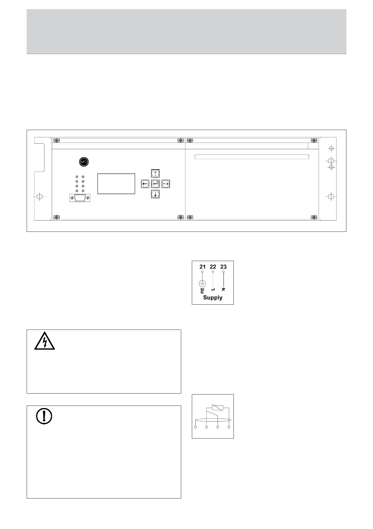
A 19“ subrack of double width (84TE) is available for
integration into the motor drive ED of a MR on-load tap-
changer or any other switching cabinet application.
Installation is the same as previously described for the 19“
subrack in chapter 3.2. Please refer to the appendix for all
relevant dimensions.
44
44
4
Electrical ConnectionElectrical Connection
Electrical ConnectionElectrical Connection
Electrical Connection
The EPT202 must be connected as shown in the device-
specific connection diagrams in the appendix (see chap. 9.5
to 9.7). The individual connections will now be described in
more detail below. The numbering of the terminals is deviating
between the EPT202 for rail mounting and the EPT202 for
panel mounting or 19“ rack. The numbering for panel
mounting and 19“ rack is given in brackets in the following
describtion
WARNINGWARNING
WARNINGWARNING
WARNING
Make sure that the electrical connection of the EPT202
and particularly the grounding is performed carefully.
Otherwise there is a danger to life!
Do not switch on the supply voltage until the electrical
connection has been made correctly.
POWER
TRIP
ERROR
ALARM
Messko
S 1
S 3
S 4
S 2
Fig. 4
44
44
4
Electrical ConnectionElectrical Connection
Electrical ConnectionElectrical Connection
Electrical Connection
NOTENOTE
NOTENOTE
NOTE
The EPT202 was developed in accordance with applicable
EMC standards. To maintain the EMC characteristics, the
following points must be adhered to.
•Ensure that the EPT202 is properly grounded via the
grounding connection on the device.
•Use the shielded cables for the data and signal
connection from the EPT202 to other devices. Ground the
shield to the terminals provided for this purpose.
4.14.1
4.14.1
4.1
Supply VSupply V
Supply VSupply V
Supply V
oltageoltage
oltageoltage
oltage
The EPT202 is equipped with a wide-range
input: 100 to 240 V AC or 100 to
353 V DC. Connect the supply voltage to
terminals 22 (42) L and 23 (41) N and the
grounding to terminal 21 (43) PE.
4.24.2
4.24.2
4.2
Sensor InputsSensor Inputs
Sensor InputsSensor Inputs
Sensor Inputs
The EPT202 can be operated with either a Pt100 or a 4-20mA
temperature sensor. In case, the ambient temperature is to be
recorded as well, a 4-20MA sensor must be used.
Measurement of the Top-Oil temperature is then achieved by
means of a Pt100 sensor.
4.2.14.2.1
4.2.14.2.1
4.2.1
Pt100-Signal (RTD) using 2 or 3 conductor wirePt100-Signal (RTD) using 2 or 3 conductor wire
Pt100-Signal (RTD) using 2 or 3 conductor wirePt100-Signal (RTD) using 2 or 3 conductor wire
Pt100-Signal (RTD) using 2 or 3 conductor wire
technologytechnology
technologytechnology
technology
Sensor connection: Terminals 9 and 10
Equalizing line: Terminal 8
Shield: Terminal 7
Caution:Caution:
Caution:Caution:
Caution: When using 2-conductor wire
technology, terminals 8 and 9 must be
jumpered!
Input Pt100
1098
7