Do you have a question about the MESSKO MTeC EPT202 and is the answer not in the manual?
All personnel involved in installation, commissioning, operation, maintenance or repair must be qualified and observe instructions.
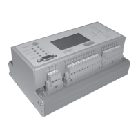
Device indicates oil and winding temperature for transformers, reactors or tap-changers.
User adherence to national accident prevention regulations is mandatory. Work on active parts is permitted only when safe.
Device available in 4 models: rail, 19" rack, control panel, and 19" subrack for motor drive.
Device indicates oil/winding temp, min/max values, load current; data logging; thermal image simulation.
Details on housing types (rail, 19" subrack, control panel) and their specifications.
Operation and storage temperature ranges.
Details on operator keys, display, LEDs, and terminal types.
Details supply voltage, power consumption, temperature sensor, and CT input specs.
Details analog outputs for oil and winding temperature, including settable ranges.
Details RS232, RS485, and SPI bus interfaces.
Details contact capacity for switching, alarm, trip, and error relays.
Specifies electrical safety, EMC, and climate resistance standards.
Lists parameters, remarks, and step sizes for various settings like temperature, data logging, and addresses.
Instructions for mounting the device on a rail according to EN 60715.
Instructions for installing the EPT202 in a 19" cabinet system.
Instructions for panel cutout and securing the device for control panel installation.
Describes installation in a double-width 19" subrack for motor drive ED or switching cabinets.
Details wide-range input voltage and connection terminals for supply.
Explains operation with Pt100 or 4-20mA sensors and ambient temperature recording.
Specifies sensor connection terminals and shielding for Pt100 sensors.
Details sensor connection for active 4-20mA sensors and max load.
Details sensor connection for passive 4-20mA sensors, including supply voltage.
Instructions for connecting CT transformer lines and deactivation option.
Explains parameterization of analog outputs for oil/winding temperature and error signal.
Details RS232 and RS485 interfaces for PC connection and parameterization.
Details RS485 data lines, ground connection, shield, and subsystem setup.
Explains connection of switching contacts S1 to S4 and their use for cooling stages.
Describes the use of alarm and trip contacts for messages or transformer tripping.
Explains the error contact function, its switching behavior, and use for error messages.
Device measures transformer temperatures and calculates thermal image (Hotspot) using IEC/ANSI standards.
Covers Pt100 or 4-20mA sensor selection and ambient temperature recording.
Details parameterization of analog outputs for oil/winding temperature and error signal.
Explains how the device monitors itself for errors like defective sensors or voltage issues.
Describes the use of 4 relay contacts for fans/pumps, controllable by temperature or manual operation.
Details storing winding parameters for 5 cooling stages including CT current, gradient, exponent, and time constant.
Explains how fans/pumps are loaded equally and switched sequentially based on load change interval.
Describes the two additional contacts for alarm/trip generation, configurable via temperature.
Explains calculation of transformer winding insulation life based on thermal aging and hotspot temperature.
Details the IEC 354 algorithm for calculating life consumption based on thermal aging.
Explains the internal memory for storing data, events, and parameters, and loading via software.
Describes disabling winding temperature simulation and related functions for oil-temperature-only operation.
Describes the front panel layout, LCD display, operator keys, and PC connection via D-Sub plug.
Explains navigating menus, changing parameters, and the temperature indication mode.
Explains how device errors (sensor defect, analog output errors, power down) are indicated.
Details how to release the key lock and change the device's key code.
Explains how to navigate from temperature indication mode to the main menu.
Describes how to select main menus using left/right keys.
Explains how to highlight and select individual menu items using UP/DOWN keys.
Menu for configuring inputs/outputs and masking winding temperature calculation.
Details selecting the input sensor (Pt100 or 4-20mA).
Describes how to parameterize analog outputs for oil and winding temperature.
Explains activating ambient temperature recording.
How to mask winding temperature calculation and related functions.
Menu for entering winding parameters for temperature and life calculation.
Setting the rated CT current for each cooling stage.
Setting the gradient, the temp difference between oil and winding at rated load.
Setting the winding exponent for calculating winding temperature rise.
Setting the thermal time constant for oil.
Menu for setting switching points for S1-S4, ALARM, and TRIP.
Setting the interval for load change operation.
Setting the temperature value for switching contacts.
Setting the hysteresis for switching contacts to prevent rapid cycling.
Setting a time delay for switching contacts.
Assigning contacts to load change mode.
Storing manufacturer-specific data like device type, serial number, and software version.
Displaying operator information and setting RS485 address.
Setting up test function, zero point correction, and temperature offset correction.
Testing relays of switching points, alarm, and trip contacts.
Correcting zero point errors caused by sensor installation.
Correcting temperature losses on the thermometer pocket.
Indicating the actual load current derived from CT input.
Specifying the load factor K based on load and rated current.
Parameterizing data logging function and reading stored records.
Setting the current time and date for the device.
Indicating data record count and setting data logging interval.
Parameterizing life consumption calculation and indicating hotspot temp/life consumption.
Selecting calculation algorithm (ANSI/IEC) or masking the calculation.
Parameterizing the expected lifespan of the transformer insulation system.
Displaying current lifespan consumption.
Storing and viewing min/max values for oil temp, winding temp, and load current.
Steps to install the EPT202 monitor software from CD-ROM.
Describes the software screen layout: menu items, left pane, and EPT202 monitor.
Details states and parameters viewable in the Monitor field: switching points, alarm/trip status, test mode, lock status.
Overview of menu items like Exit, Disconnect, Parameter, Settings, User, Switching point, Winding, Device data.
Configuring language, password, connection type (RS232/RS485), and interface.
Functions for loading/saving parameters, and printing device data protocols.
Features for zooming, paging, formatting, and printing data.
Making basic settings: zero point correction, sensor loss correction, MIN/MAX values.
Configuring ambient temp recording, oil temp input, analog outputs, and winding configuration.
Reading data records, setting interval, and managing date/time.
Parameterizing life consumption, selecting algorithm, and setting expected lifespan.
Configuring contacts S1-S4, Alarm, and Trip with description, control, switching point, hysteresis, delay.
Setting winding parameters: rated CT current, gradient, exponent, time constant, hotspot factor, CT-Ratio.
Using Easy Set function for simplified parameterization of cooling stages per IEC 60354.
Storing manufacturer data and user-specific information like transformer location.
Provides dimensional drawings for rail mounting configuration.
Provides dimensional drawings for 19" rack mounting configuration.
Provides dimensional drawings for control panel mounting configuration.
Provides dimensional drawings for installation in motor drive ED.
Shows connection diagram for top-hat rail mounting.
Shows connection diagrams for panel and 19" subrack installation.
Provides circuit diagram for connecting 4-20mA sensors.
Provides circuit diagram for connecting Pt100 sensors.
| Brand | MESSKO |
|---|---|
| Model | MTeC EPT202 |
| Category | Thermometer |
| Language | English |