11
BA 2076/02/01
4 Electrical connection
4.2.24.2.2
4.2.24.2.2
4.2.2
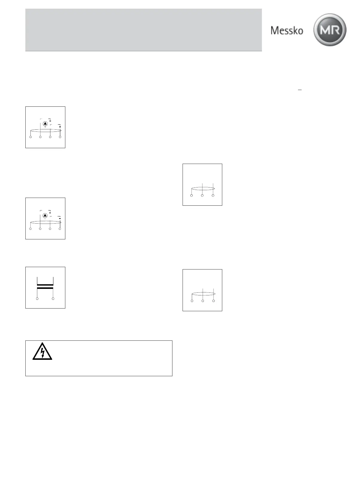
4 to 20 mA active Sensor I4 to 20 mA active Sensor I
4 to 20 mA active Sensor I4 to 20 mA active Sensor I
4 to 20 mA active Sensor I
11
11
1
Input I
1
has an internal voltage supply for a sensor with
4 to 20 mA output and
no ownno own
no ownno own
no own voltage supply
(e.g., MT-ST160SK/TT)
Sensor connection (+): Terminal 12
Sensor connection (-): Terminal 13
Shield: Terminal 11
Caution:Caution:
Caution:Caution:
Caution: Adhere to the maximum load of
the sensor and the circuiting.
4.2.34.2.3
4.2.34.2.3
4.2.3
4 to 20 mA passive Sensor I4 to 20 mA passive Sensor I
4 to 20 mA passive Sensor I4 to 20 mA passive Sensor I
4 to 20 mA passive Sensor I
22
22
2
Input I
2
is designed for a sensor with 4 to 20 mA output and
its
ownown
ownown
own voltage supply (e.g., TT-PWM60).
Sensor connection (+): Terminal 13 (8),
Sensor connection (-): Terminal 14 (7),
Shield: Terminal 11 (10)
Supply voltage: 24 VDC ± 10%
Caution:Caution:
Caution:Caution:
Caution: Adhere to the maximum load of
the sensor and the circuiting.
4.44.4
4.44.4
4.4
Analog OutputsAnalog Outputs
Analog OutputsAnalog Outputs
Analog Outputs
The analog outputs for oil and winding temperature can be
parameterized as desired to the following values.
• 0 to 10 V
• 0 to 1 mA
• 4 to 20 mA (error signal < 3.6 mA)
• 4 to 20 mA (error signal > 22 mA)
• 0 to 20 mA (error signal > 22 mA)
The error signal is output on the analog output when the
input sensor is defective.
With the current outputs, the maximum load (total resistance
of the lines and connected devices) of 750 W may not be
exceeded. The internal voltage supply is 24 V DC
+10%. When
a current output is not used, its terminals (+) and (-) must be
jumpered. Otherwise an error message is output.
When an analog output is parameterized to 0 - 10 V, this
must be loaded with at least 1 kW. The voltage output may not
be jumpered. An open or defective voltage output is not
detected.
Analog output 1 “Output Oil-TAnalog output 1 “Output Oil-T
Analog output 1 “Output Oil-TAnalog output 1 “Output Oil-T
Analog output 1 “Output Oil-T
emp“emp“
emp“emp“
emp“
Line connection (+): Terminal 2
Line connection (-): Terminal 3
Shield: Terminal 1
The range of analog output 1 corresponds
to the input range of the sensor (refer to
nameplate), standard: -20 to +140 °C.
Example: 4 to 20 mA output:
4 mA corresponds to -20 °C
20 mA corresponds to +140 °C
Analog output 2 “Output Winding“Analog output 2 “Output Winding“
Analog output 2 “Output Winding“Analog output 2 “Output Winding“
Analog output 2 “Output Winding“
Line connection (+): Terminal 5
Line connection (-): Terminal 6
Shield: Terminal 4
The range of analog output 2 is specified
on the nameplate (standard: 0 to +160 °C).
Example: 4 to 20 mA output:
4 mA corresponds to 0 °C
20 mA corresponds to +160 °C
4.54.5
4.54.5
4.5
Digital interfacesDigital interfaces
Digital interfacesDigital interfaces
Digital interfaces
To be able to parameterize the EPT202 with the visualization
software and call up the data, the EPT202 must be connected
via an interface with a PC. The following interfaces are
available for this purpose.
• RS 232
• RS 485 (bus-capability)
Input 4...20mA
14
13
1211
I
1
+
I
2
+
Output
Winding
+
-
65
4
Output
Oil Temp.
+
-
321
Input 4...20mA
14131211
I
1
+
I
2
+
RS 232RS 232
RS 232RS 232
RS 232
To transmit data between a PC and the EPT202 via the RS
232 interface, connect the RS 232 interface of the PC (or an
interface converter) with a suitable 9-pin connection cable to
the sub D plug connector on the front of the device.
WARNINGWARNING
WARNINGWARNING
WARNING
High voltage, when the CT lines are disconnected and the
transformer is operating.
4.34.3
4.34.3
4.3
CT Input (Secondary CurrCT Input (Secondary Curr
CT Input (Secondary CurrCT Input (Secondary Curr
CT Input (Secondary Curr
ent Tent T
ent Tent T
ent T
rr
rr
r
ansformer)ansformer)
ansformer)ansformer)
ansformer)
Connect the lines of the CT transformer to
terminals 15 and 16.
If the EPT202 is equipped with a split core
transformer, then it must also be connected
to terminals 15 and 16.
This input can be deactivated during
parameter assignment so that only the oil
temperature is indicated, for example.
CT
15 16