34 BA 2076/02/01
8.98.9
8.98.9
8.9
<Switching points> Menu<Switching points> Menu
<Switching points> Menu<Switching points> Menu
<Switching points> Menu
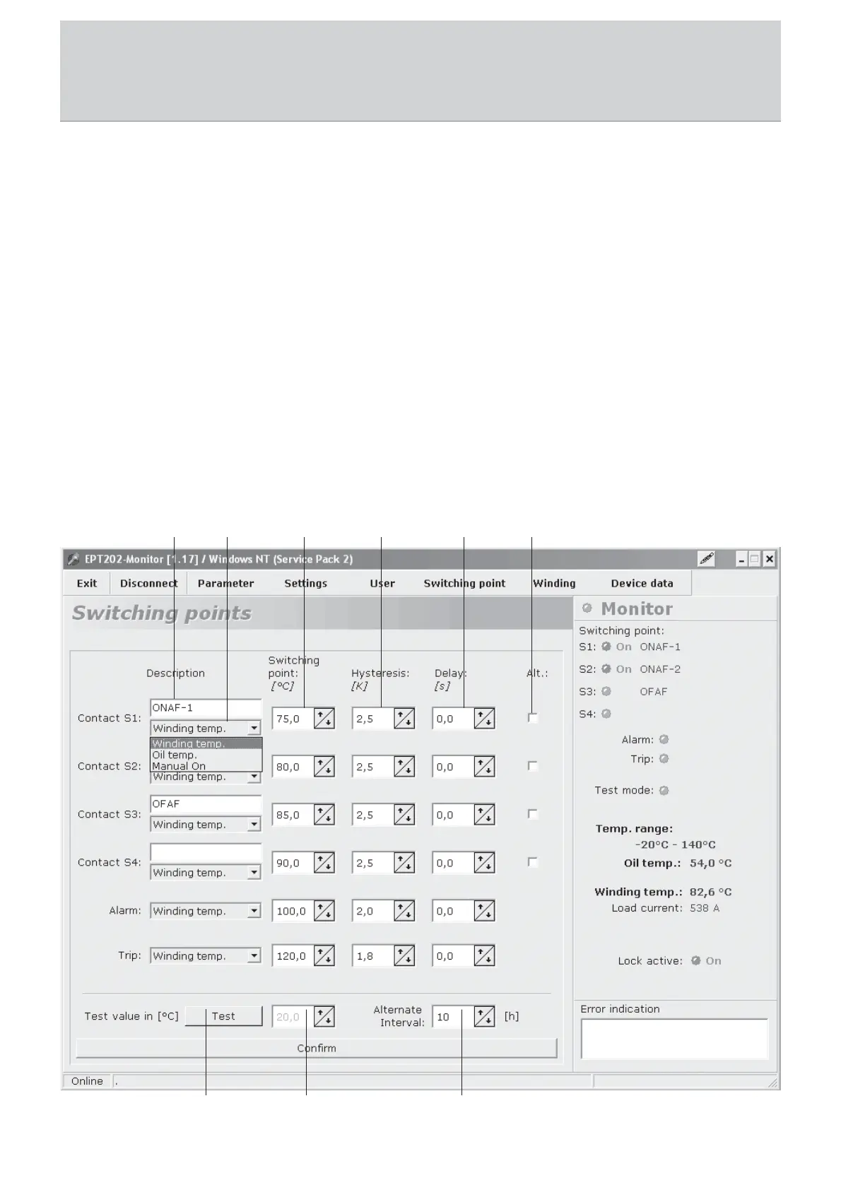
Contacts S1 to S4 for cooling system control and the Alarm and Trip contacts are configured in the switching points menu. The
parameterization of the individual fields is described below.
1) Description: 1) Description:
1) Description: 1) Description:
1) Description: A description (e.g., the designation of the cooling stage, here ONAF1) can be assigned in a text field for each of
the contacts S1 to S4.
2) Control of the contacts:2) Control of the contacts:
2) Control of the contacts:2) Control of the contacts:
2) Control of the contacts: The contacts can be activated via the oil or the winding temperature. This means that when the oil
or winding temperature exceeds the set switching point, the contact (change-over contact) is switched. When switched back,
the contact drops below the switching point hysteresis. Contacts S1 to S4 can also be switched permanently with <Manual on>.
3) Switching point:3) Switching point:
3) Switching point:3) Switching point:
3) Switching point: The switching points can be set as desired. When you activate the contacts via the oil temperature, ensure
that the switching point setting is within the range of the sensor input. If the contact is not to be used, we recommend setting
the switching point to the end value.
4) Hysteresis:4) Hysteresis:
4) Hysteresis:4) Hysteresis:
4) Hysteresis: The hysteresis cannot be set to 0. The smallest possible hysteresis is 1% of the input range. The maximum
hysteresis which can be set is calculated from the switching point so that the contact can still be switched back within the
input range.
8 Visualization Software
1 2 3
4
5 6
7
8 9