5
BA 2076/02/01
1 General
11
11
1
GenerGener
GenerGener
Gener
alal
alal
al
1.1.1.1.
1.1.1.1.
1.1.
Safety InstructionsSafety Instructions
Safety InstructionsSafety Instructions
Safety Instructions
All personnel involved in installation, commissioning,
operation, maintenance or repair of the equipment must
· be suitably qualified and
· strictly observe these operating instructions.
Improper operation or misuse can lead to
· serious or fatal injury,
· damage to the equipment and property of the operator
and
· a reduction in the efficiency of the equipment.
Safety instructions in this manual are presented in three
different forms to emphasize important information.
WARNINGWARNING
WARNINGWARNING
WARNING
This information indicates particular danger to life and
health. Disregarding such warnings can lead to serious or
fatal injury.
1.21.2
1.21.2
1.2
Use as SpecifiedUse as Specified
Use as SpecifiedUse as Specified
Use as Specified
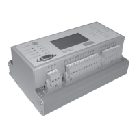
Together with a temperature sensor, the EPT202 device from
the MTeC® series indicates the oil and winding temperature
of oil-insulated transformers, reactors or on-load
tap-changers. The device can be used to control the individu-
al cooling stages based on load and temperature and, in
emergencies, shut down the entire transformer.
Before commissioning the device, it is essential to read and
adhere to the limit values for the application specified on the
nameplate and operating instructions.
1.31.3
1.31.3
1.3
Notes on the Operation of the DeviceNotes on the Operation of the Device
Notes on the Operation of the DeviceNotes on the Operation of the Device
Notes on the Operation of the Device
User adherence to national accident prevention regulations is
mandatory.
It is also pointed out that work on active (i.e., parts which are
hazardous to touch) is only permitted when these parts are
potential free or are protected against direct touch.
National regulations pertaining to electrical installation must
be observed. To ensure correct operation, it is essential to
connect the protective conductor (PE).
1.41.4
1.41.4
1.4
DesignDesign
DesignDesign
Design
The device is available in 4 models.
- Compact device in an aluminum housing for installation on
a rail in accordance with EN 60 715 TH 35-7.5 and
TH 35-15
- 19" Rack (3 HE, 42 TE, depth: 176 mm) for insertion in a
19" cabinet system
- Device for control panel installation with panel cutout,
236 mm x 142 mm
- 19" subrack for installation in the motor drive ED of the
MR on-load tap-changer
The electrical connection is performed with plug-in
connectors in accordance with DIN 41 612. An SPI interface
is available on the side of the device for the connection of
extra modules (OL/CT).
NOTENOTE
NOTENOTE
NOTE
These notes provide important information on a certain
topic.
CAUTIONCAUTION
CAUTIONCAUTION
CAUTION
This information indicates particular danger to the
equipment or other property of the operator, risk of
serious or fatal injury.
CAUTIONCAUTION
CAUTIONCAUTION
CAUTION
Make sure that all power supplies leading to the digital
thermometer are disconnected at the switchgear cubicle
before doing impulse voltage testing or any other kind of
applied voltage testing to the transformer.
NOTENOTE
NOTENOTE
NOTE
When using the additional modules EPT202OL, EPT202CT or
EPT202OL/CT, please refer to the operating instructions
BA2078.

 Loading...