25
BA 2076/02/01
8 Visualization Software
8.38.3
8.38.3
8.3
The EPT20The EPT20
The EPT20The EPT20
The EPT20
2-Monitor2-Monitor
2-Monitor2-Monitor
2-Monitor
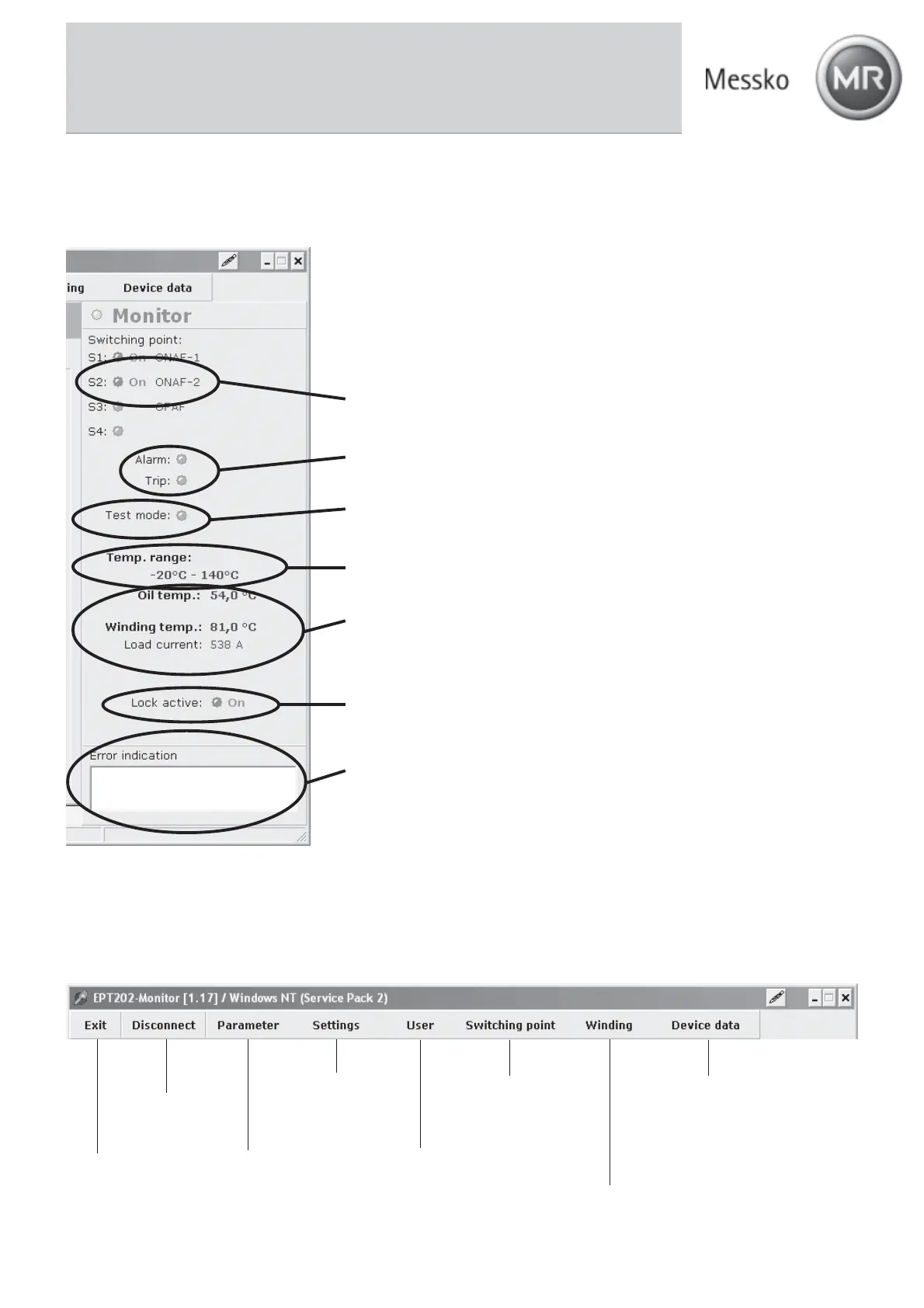
The following states and parameters can be viewed in the <Monitor> field:
Status of contacts S1 to S4 (red = on: contact is circuited) and designation of the
assigned cooling stage (ONAF1 1 here).
Status of the ALARM and TRIP contacts (red = on: contact is circuited).
Status of test mode (red: test mode is activated via the software or via .
the device)
Input range
Current oil temperature, winding temperature and actual load current
Status of the key lock (red = on: key lock on device locked, off: key lock on device
released)
The <error indication> shows the device errors (e.g., defective sensor).
8.48.4
8.48.4
8.4
Menu BarMenu Bar
Menu BarMenu Bar
Menu Bar
The individual menu items are briefly discussed below. For a detailed explanation, see the next few chapters.
Exit
program
Connect /
disconnect
the device
Load, save and
print the
parameter records
Change the default
settings (e.g. language)
User-specific settings
(e.g., input and output
configuration)
Setting of the
switching points
Setting of the winding
parameters
Call and save the
device data
(e.g., date of
manufacture,
RS485 address)