Installers manual 10.03.02-R03 (201058) EN SDA-04 (SW 5.xx) - SDA-04DCB2 (SW 22.00) Page 13 of 55
5. Installation, maintenance and dismantling
5.1 Installation
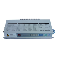
5.1.1 Assembly of the controller
The SDA-04 controller must always be fitted with the heatsink on top. Take care to ensure that the
heat produced by the controller can be dispersed sufficiently. The SDA-04DCB2 has no external
heatsink. The above is therefore not applicable.
The controller has two attachment points on the top and bottom.
These can be used to attach the controller to the rail and within an external housing.
5.1.2 Earth connection
The earth connection on the left side of the SDA-04 controller must be connected to the aluminium rail
upon which the door is hung. The controller must be connected to the mains power supply using the
earthed socket provided.
5.1.3 Motor connection
The motor is connected via a shielded round connector (plug connector for the SDA-04DCB2).
The outer ring of the connector must always be firmly screwed onto the controller (tighten
screws by hand; do not use tools).
1) In connection with EMC and electrical safety, the device must not be switched on if the outer ring is
not screwed on properly.
2) In connection with EMC, the motor cable should never be extended.
5.1.4 Motor pulse generator
The motor pulse generator must be connected on the rear SUB-D connector to the right side of the
controller (Plug connector for SDA-04DCB2).
1) In order to prevent uncontrolled movement of the door, the controller must
never be enabled if the pulse generator is not connected.
5.1.5 Connection sequence SDA-04