Installers manual 10.03.02-R03 (201058) EN SDA-04 (SW 5.xx) - SDA-04DCB2 (SW 22.00) Page 37 of 55
Hardware-related messages SDA-04DCB2
SDA-04DCB2 with 100 Watt DC motor at rest, no current activities and/or errors
Controller low voltage fault
Check mains supply - reset
Current surge or short circuit to earth
Replace controller and/or motor
No parameter setting/EEPROM or teaching-
in error
Reset controller / Call the service
department
Toothed belt broken or extreme structural
opening width
Fault during teaching-in process
Reset controller, check mechanical
adjustment of door
Check connections, repair / replace the
motor
Battery faulty or not found
Check connections, repair / replace the
battery
Switch the motor connections
Battery voltage is too low
Check the battery charge / replace the
battery
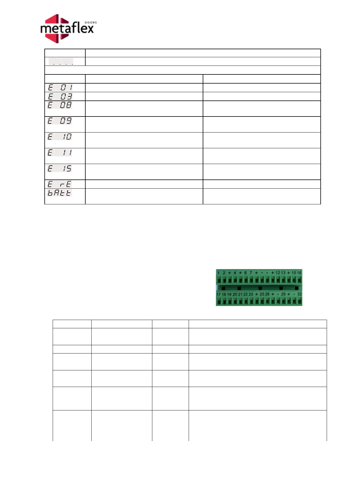
11 Electrical connections
This chapter describes all the control and protection inputs and outputs of the SDA-04. These signals
are all provided on the two green connectors on the right side of the controller. The chart below
provides each input/output terminal number, the function name, the description and an example of its
application.
11.1 Input signals of the SDA-04
Controller connector information
The inputs and outputs of the SDA-04 and the
SDA-04DCB2 are the same.
Connectors are mutually interchangeable.
This input is used to put the door in the closed
position; the SDA sends a lock signal (if present).
This input is used to block the one-way passage.
This input is used to unlock the SDA locks in an
emergency.
This input is used to switch off the electrical door
drive in an emergency.
This input is used in the event of a fire to place the
door in the 'Escape door position' or the 'Fire door
position'.
This input is used to bring the door to the 100%
open position or to allow the door to close in the
event of a 'Pulse open/close' system.
When it is 'one_way', the action is blocked.