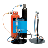
Page 33 of 64
Using a suitable drift drive out the long 3/32” Cam Lever Dowel (Q) at the end of the Cam
Spindle Housing furthest from the lever. Withdraw the Cam Spindle (R).
Unscrew the Retaining Screws (W) in the base of the Gas Head and retain these. Remove
and discard the two Filters (Y).
4.5.2 Gas Head & Valve Re-Assembly
Still Referring to DIAG 5 and DIAG 6:
Insert new filters (Y) into the fuel gas and oxygen ports of the Gas Head (V).
Secure these with two Retaining Screws (W). Ensure that the Retaining Screws do not
protrude beyond the base of the Gas Head.
Apply a multi-purpose grease to the Cam Spindle (R) and slide it fully into the Cam
Spindle Housing (I)
Refit the Cam Lever Dowel (Q).
Place the three plungers (K) in their respective apertures, including the Gas Pilot Plunger
(S) into the Gas Plunger in the centre.
After fitting new Diaphragms (J) in the Diaphragm Housing (H) secure it to the Cam
Spindle Housing (I) with the Diaphragm Housing Screws (G).
Using a new Gasket (X) refit the Valve to the Gas Head with the Valve to Gas Head Fixing
Screws (E).
Check that Union Washers (U) are intact and secure the Air Union (C), and Oxygen Union
(D) to the valve.
NOTE: If the Gas Union (T) gets removed for whatever reason, note that when re-fitting, it
has a left hand thread.
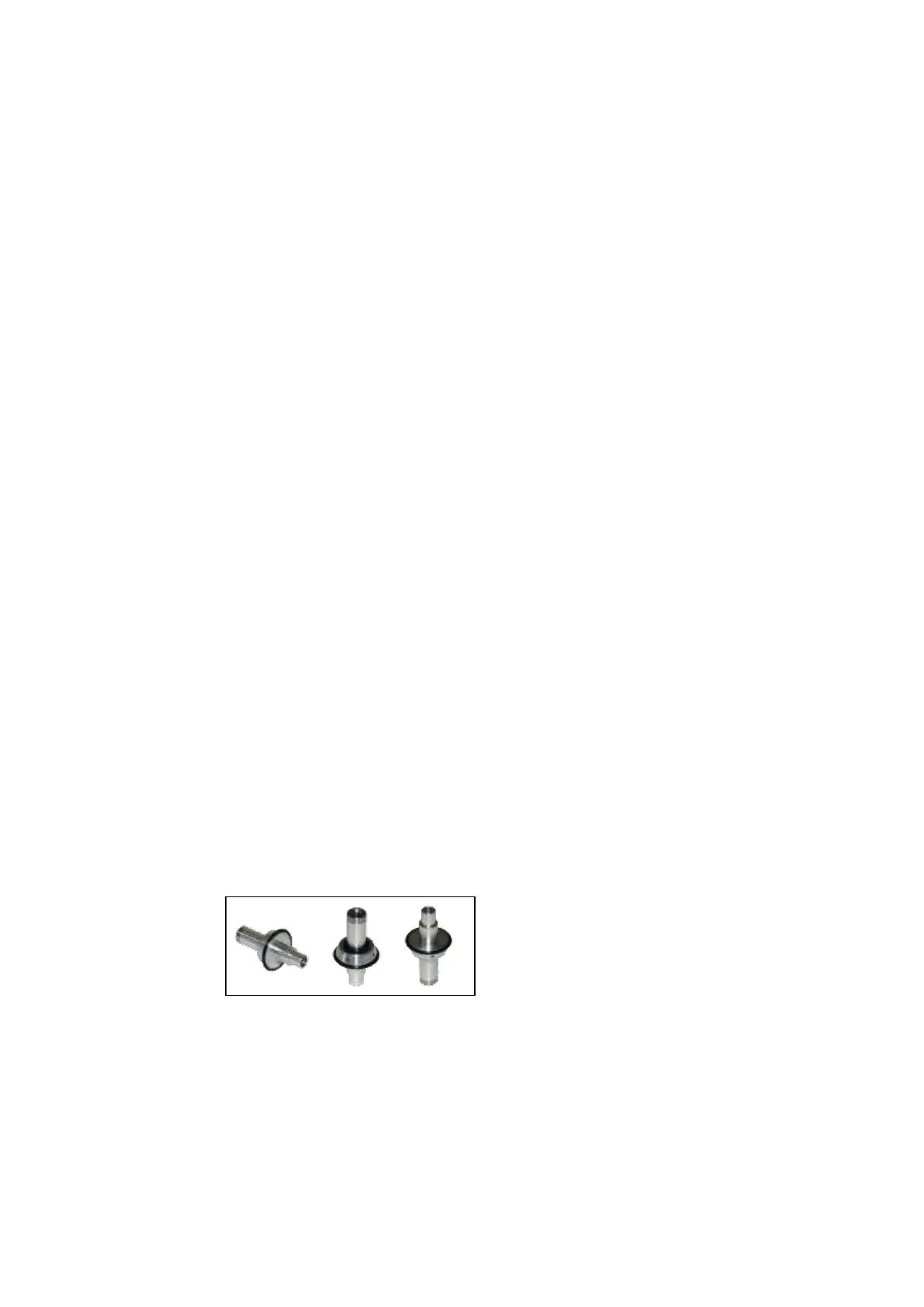
Take the Front Wire Guide (appropriate for the size of wire to be sprayed) complete with
inner and outer ‘O’ Rings (Parts 1007 and 1008). Ensure that the ‘O’ Rings are fitted
correctly to the Front Wire Guide. See DIAG 7 below for an example of this:
Slide the Front Wire Guide into the rear of the Gas Head then secure the Gas Head to the
Pistol Body with the Gas Head Fixing Screws.
Fit the Lever Return Spring (P) and Cam Lever (M) so that the Lever handle hangs
downwards when the Cam Spindle (R) is turned fully clockwise. Secure with the Valve
Lever Screw (N) and the Washer (O) and refit the Valve Lever Plug (L).