38
SERVICE
12. Use tweezers to remove a piece of filter paper from the plastic bag.
NOTE: Do not touch the filter paper. Skin oils will contaminate the disk, resulting in improper readings.
13. Add one drop of DI to the filter paper to saturate it.
14. Allow the water a couple moments to fully absorb into the filter.
15. Still holding the disk with the tweezers, quickly flick the wrist to remove any excess
water.
The paper should glisten, but no water drops should be clinging to the disk.
The wetness state of the filter paper is critical for an accurate calibration. The paper
must be wet enough to provide a 100% RH surface. However, if the paper is too wet, free
water will be pulled into the calibration plate hole by surface tension and will change the
effective dimensions of the hole and its conductance.
16. Lay the filter paper flat over the hole in the calibration plate on the side marked Filter
Paper. Make sure the paper completely covers the hole but does not cave into or bubble
out from it.
The plastic calibration plate has a known conductance of 240 mmol/(m
2
s). It is critical
that the filter paper be properly placed for this conductance value to be correct.
17. Turn the calibration plate over and carefully examine the hole to make sure that no
meniscus of water is present in the hole.
If excess water is observed, remove the filter paper, dry the calibration plate, and repeat
step13 through 17.
NOTE: If the filter paper becomes too dry to adhere to the calibration plate, it will need to be wet again and the
calibration procedure will need to be restarted.
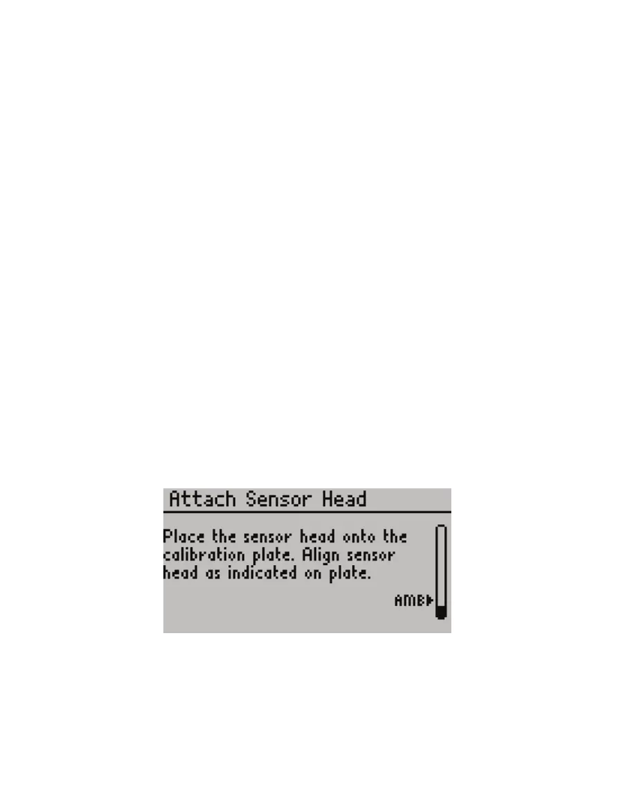
18. Press ENTER on the SC-1 controller.
The Attach Sensor Head screen will appear (Figure50).
Figure50 Attach Sensor Head screen
19. Slide the calibration plate into the sensor head, orienting the side of the plate marked
Metal Block toward the aluminum block side of the sensor head (Figure51). A seating
click will occur when the plate is placed correctly. The lip on the calibration plate should
be fully fitted into the top of measurement hole.