Place the prepared rolling diaphragm (7) on the
spring retainer (41) of the spring package. Also,
place the diaphragm support plate (6) and the new
seal ring (51) on the rolling diaphragm.
Next, attach the spring package to the end of the gear
rod (4) by turning it by the fixed nut (54). Check, at the
same time, that the welded nut is intact. Tighten the
spring package with the nut (54) according to the
torque values given in Table 3. Secure the connection
by using Loctite 243 or similar.
Stretch the seal ring of the rolling diaphragm (7) into
the groove in the spacer plate (45) as described in
Section 4.2.1.
Install a new bearing (49) in the bearing slot of the
spring retainer (41).
Press the spring housing (42) until it touches the spacer
plate (45) while making sure that the bearing (49) remains
in its slot during the installation. Also, check that the seal
ring at the edge of the rolling diaphragm (7) remains in
the seal groove of the spacer plate (45), and that the edge
folds nicely inside the spring housing. If the folded rolling
diaphragm does not fit well in the spring housing, lubricate
lightly with Unisilikon GLK112 or Molykote III lubricant.
Tighten all socket head screws (53) evenly accord-
ing to the torque table.
Install the stop screws (23) and nuts (24) at the end
of the spring housing (42) and the cylinder (2).
Finally, the required activator operation range is
adjusted with the stop screws (23) and nuts (24).
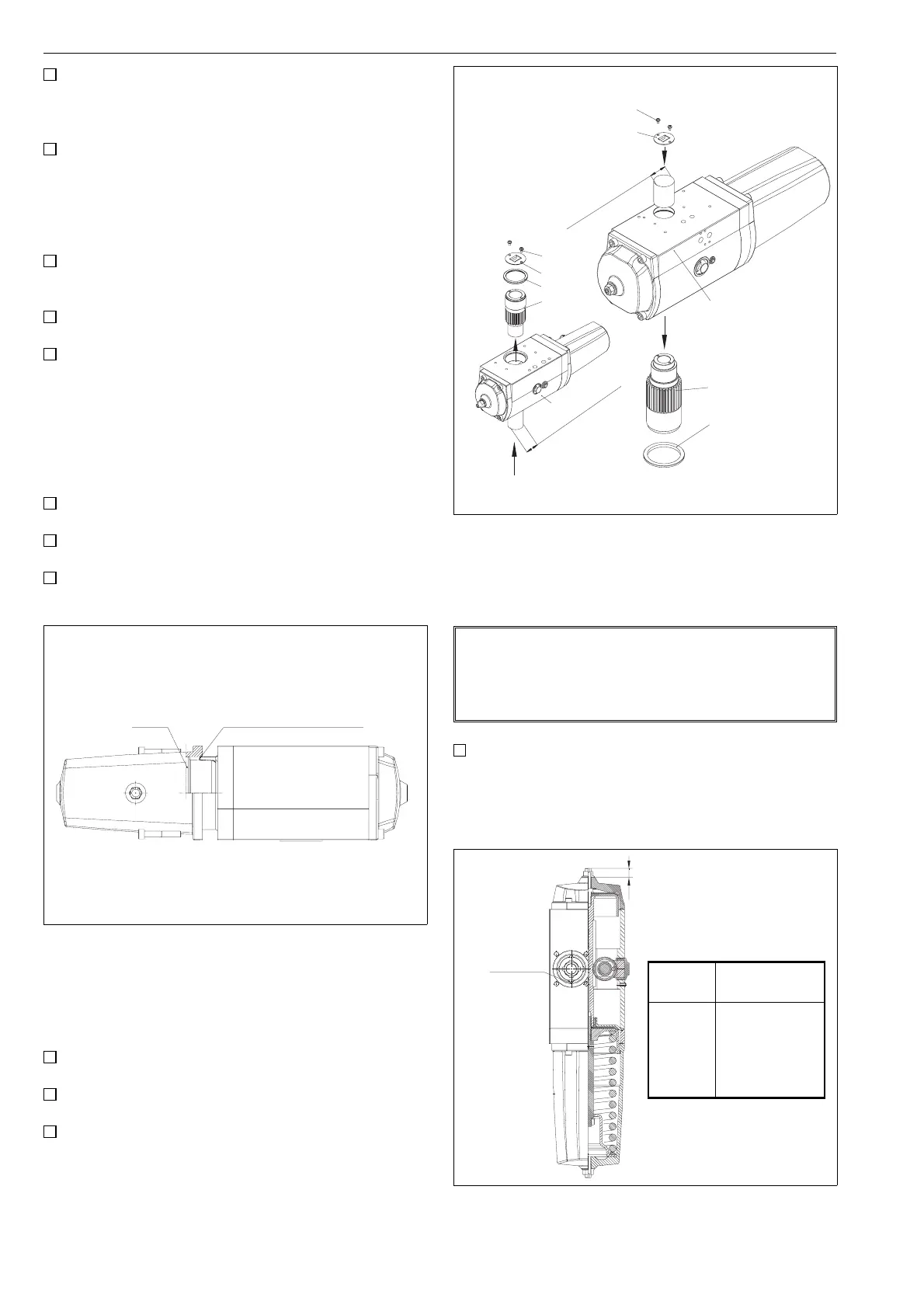
4.2 Detaching and attaching the drive shaft
Exchange of drive seal rings is carried out according to the
following procedure:
Detach the actuator from the valve and the positioner
or any other accessory from the actuator.
Remove the cross rec head screws (27) and the
coupling plate (15) from the top of the drive shaft (3).
Make a note of the drive shaft (3) position before detach-
ment. This can be done by marking the drive shaft position
in relation to the actuator housing (1). Marking can be done
using a marker or paint dots. Remove from the housing (1)
the drive shaft (3) and the guidance ring (16) which has
been attached with a pressure adapter, by using a
suitable tool, such as a hydraulic press.
NOTE:
Detaching the drive shaft from EJ05 occurs in a direction
that is different to that for other sizes, see Figure 20.
Removal of the EJ14 drive shaft also removes one of
the needle bearings.
Exchange the O-rings (35, 36) of the needle bear-
ings. During the exchange, it is important to add
lubricant (Exxon Unirex S2 or similar) to the O-rings
and needle bearings.
Bearing strip
in its groove
Unisilikon GLK 112 or Molykote III
in the membrane fold if necessary
Fig. 19 Installing the spring housing
Cylindrical pin
ø30 mm (max)
Cylindrical pin
ø40 mm (max)
27
15
F
27
15
31
3
EJ05
F
EJ07-14
1
3
16
1
Fig. 20 Detaching the drive shaft
Chiseled
mark
Y
Fig. 21 Determining drive shaft position
Type Y-measurement
mm / inch
EJ05
EJ07
EJ10
EJ12
EJ14
18 / 0.71
19 / 0.75
23.5 / 0.92
27.5 / 1.08
35.5 / 1.40
10