The actuator design allows axial movement of the drive
shaft. Check, before the screw is tightened, that the drive
shaft is in the upper position of its axial movement, which
is its normal position (the mounting position shown in Figure
8). Checking is important, as the actuator shaft drops down
slightly when the screw is tightened. The axial movement
of the drive shaft can be observed and measured before
attachment to a valve. The actuator drive shaft is in the
upper position when its upper surface conforms to Table 2
(see Figure 8).
The drive shaft will automatically find its correct position
when the tightening screw is tightened, if the installation tool
is used (See Figure 8). The installation tool is attached
instead of the coupling plate using M4 screws with the drive
shaft in upper position (before the valve is installed). Tighten
the screws in such a way that the tool is tightened against
the upper surface of the housing.
Install the actuator on the valve and attach the attachment
screws normally. Finally, tighten the tightening screw ac-
cording to Table 2. The required torque is also marked on
a plate close to the drive shaft on the actuator housing. The
installation tool is removed, and the coupling plate is reat-
tached.
The valve may malfunction if the tightening of the connec-
tion has been carried out improperly.
Finally, the extreme positions of the valve are adjusted with
the stop screws at the ends of the actuator. The location of
the screws for adjusting the Close and Open positions of
the valve are marked with letters on the ends of the actuator
housing (see Figure 5).
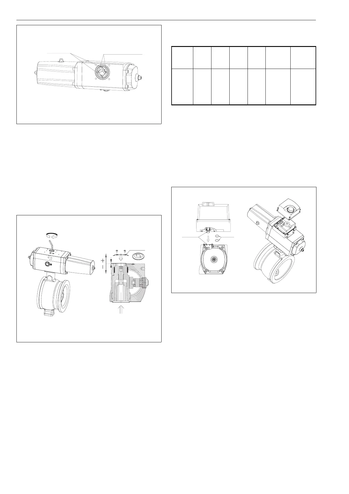
3.3 Attaching the ND800 valve controller
to the actuator
The ND800 valve controller is attached directly to the
actuator with four attachment screws. No tubing is required
between the devices. Two of the attachment screws are
located at the front of the actuator and two below the cover.
O-rings are placed in the air connections of the positioner.
The valve controller shaft is correctly positioned when the
painted position marks are aligned (see Figure 9).
External tubing is necessary if a reverse signal function is
required. See the ND800 installation, user and mainte-
nance instructions 7 ND 70 for further information.
Attachment of the ND800 valve controller to the EJ05
actuator is done using a connection plate (see Figure 10).
Make sure that the pegs of the connection plate are pointing
away from the actuator. The plate is attached to the actuator
with four attachment screws. In addition, O-rings are placed
in the grooves below the plate. The ND800 valve controller
is attached next, as described previously.
Size Mount. Thr. Hex.
size
Nm ~X
upp. pos.
(mm)
~X
lower pos.
(mm)
EJ05
EJ07
EJ10
EJ12
EJ14
F05
F07
F10
F12
F14
M12
M16
M20
M24
M36
6
8
10
14
19
25
50
100
200
700
4,0
1.5
2.5
3.5
4.5
1
-2
-2
-2
-2
Table 2. Mounting interfaces, tightening screws, tight-
ening torques and drive shaft movement
DIN keyways in the
middle of bushings
ANSI keyways at the
bushing split
THE ACTUATOR IN CLOSED POSITION
Fig. 7 Keyway positions on the actuator
X
Installation
tool
Fig. 8. Tightening of the cone bushing
O-rings
Painted
alignment
marks
Fig. 9. Attaching the ND800 valve controller to
the EJ actuator
6