Fix the cylinder end with the socket head screws (22),
once it is in the right position. Tighten the screws
according to the torque values given in Table 3.
4.1.2 Exchanging diaphragm at the spring end
WARNING:
Do not dismantle a pressurized actuator!
The seal ring (50) should be exchanged together with the
membrane. Bearings (47, 49), O-rings (20, 59, 52) and seal
ring (51) are exchanged when required.
The diaphragm in the spring-less end is exchanged in the
following way:
Make sure that the actuator is depressurized.
Remove the nut (24) and the stop screw (23) from the
end of the spring housing (42). Remove the nut (24)
and the stop screw (23) from the cylinder end (2) also.
Remove the socket head screws (53) of the spring
housing (42) by gradually and sequentially turning
each one. The spring housing will maintain the com-
pression of the spring package.
Turn the screws evenly (ca. 5 mm or 3 full turns) until the
spring housing (42) has released the spring package
compression. Then remove the socket head screws (53)
completely from the housing (1).
Remove spring housing (42), spacer plate (45), O-
ring (52) and O-ring (20) from the housing (1).
Remove the bearing (49) from the spring package and
remove the package from the gear rod (4) by turning it
open. The spring package can also be turned by the
nut (54) at the end of the package. The nut has been
permanently fixed and must not be detached from
the spring package.
WARNING:
The spring package must not be dismantled, as the
spring will still be compressed after the package has
been detached.
Following the detachment of the spring package, the
following parts can be removed from the gear rod
(4): rolling diaphragm (7), diaphragm support plate
(6) and seal ring (51).
Remove the lead-through plate (46) from the gear
rod (4) by pulling it away from the housing (1).
Remove the lead-through bearing (47) from the lead-
through plate (46) and the seal ring (50) from the
lead-through bearing.
Check the lead-through bearing and replace it if it is worn.
Lubricate the new seal ring (50) with Unisilikon
GLK122 or Molykote III lubricant or similar, and install
it in the lead-through bearing (47).
Install the O-ring (59) in the groove on the outer
surface of the lead-through bearing (47). Then attach
the lead-through bearing (47) to the lead-through
plate (46) using a suitable pressing tool.
Press the lead-through plate (46), the lead-through bear-
ing (47) and the seal ring (50) onto the gear rod until the
lead-through plate (46) touches the housing (1).
Install the O-ring (20) in the groove at the end of the
housing (1).
Check and remove loose particles from the spring
retainer (41), the diaphragm support plate (6) and the
spacer plate (45) at the end of the spring package.
Lubricate the grooves in the spacer plate (45) with
Unisilikon GLK112 or Molykote III lubricant or similar,
and install the O-ring (52) in the groove.
Place the spacer plate (45) and the O-ring (52) on
the housing (1) and the lead-through plate (46).
Next the rolling diaphragm (7) is prepared as shown
in Figure 15 of Section 4.2.1.
20
24 23
2
1
4
51
46
47
50
6
7
49
54
23
24
42
53
45
52
59
Note:
Part 59: only EJ07-14
Fig. 17 Exchange of membrane at the spring end
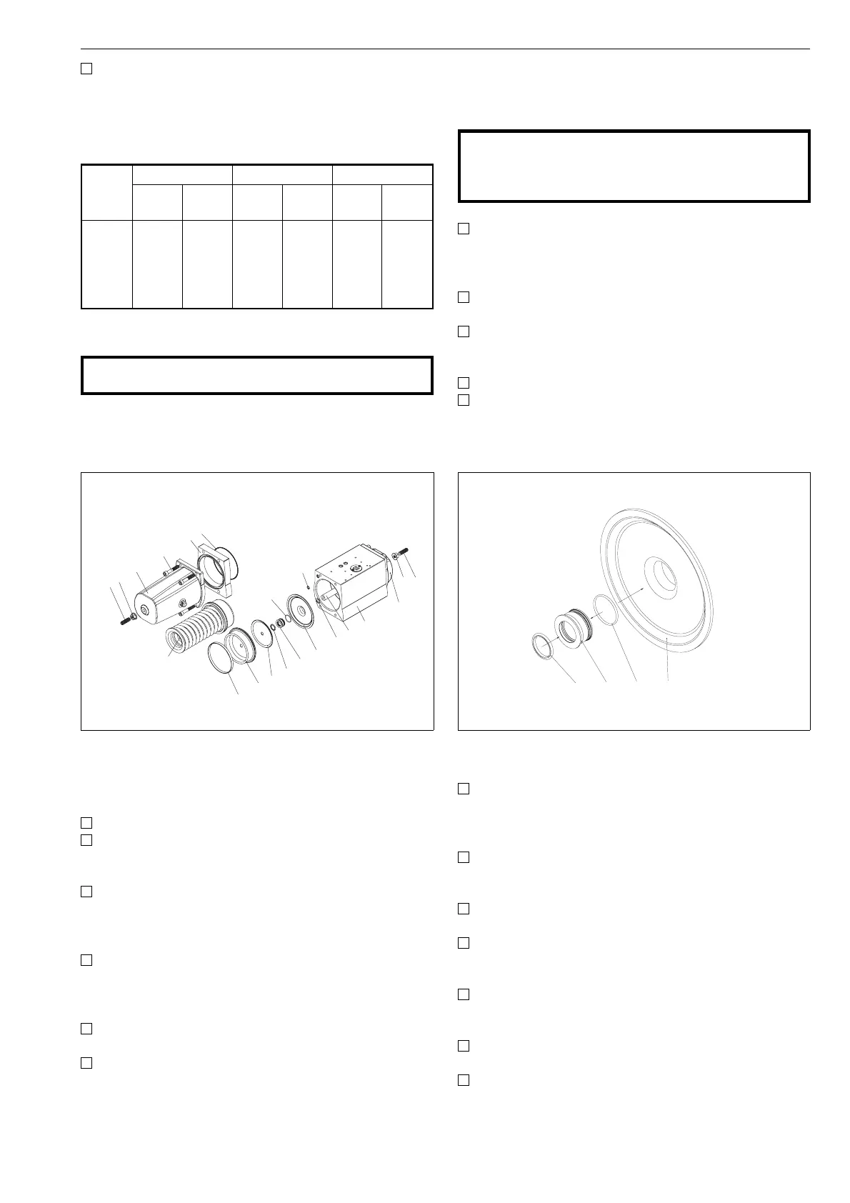
50 47 59 46
Note:
Part 59: only EJ07-14
Fig. 18 Installation of lead-through bearing and
seal ring
Actu
ator
Screw (22, 53) Screw (25) Spring package
Thread Nm Thread Nm Hex.
size
Nm
EJ 05
EJ 07
EJ 10
EJ 12
EJ 14
M6
M8
M10
M12
M16
8,3
20
40
69
170
M8
M10
M12
M16
M20
10
15
25
40
60
13
19
24
30
36
10
15
25
40
60
Table 3. Screws (parts 22, 25 and 53) and spring pack-
age, tightening torques
9