2 TRANSPORTING, RECEIVING AND
STORING
Check that neither the actuator nor its accessories have been
damaged during transportation. Store the actuator carefully
prior to installation, preferably indoors in a dry place. Do not
transfer it to the installation point or remove the end caps until
immediately prior to the installation. If the actuator diaphragms
are separately stored, storage should be carried out accord-
ing to general rules covering the storage of rubber products.
The equipment should be stored in a dry place at room
temperature, protected from UV radiation. The diaphragms
are packed in a non-transparent plastic bag that should not
be opened unnecessarily.
Lift the actuator as shown in Figure 4: In the horizontal
position by sufficiently long hexagon screws which replace
the adjustment screws, in the vertical position by an eyebolt
which replaces the adjustment screw. Check the weights
from the table in Section 9.1.
3 INSTALLATION AND DISMANTLING
3.1 Operating fluid
Double diaphragm actuators use dry compressed air or
natural gas. Oil spray is not required. Actuators equipped
with positioners use clean, dry and oil-free compressed air.
The air connections are shown in the dimensional drawing
9.2. (Dimensions). The maximum supply pressure for the
actuator is specified on the label (Figure 2). See also
Section 1.4 "Technical data".
3.2 Attaching the actuator to a valve
The actuator is attached to a valve via an ISO 5211 standard
mounting interface. The actuator bore is adapted to the
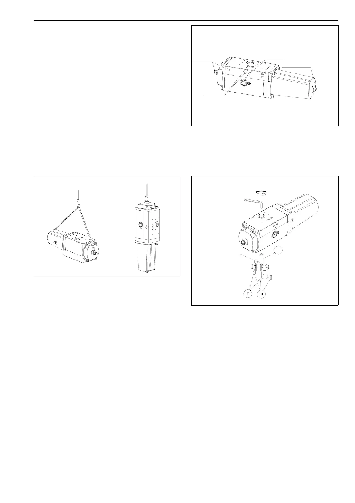
valve stem with a separate coupling. The coupling (II+II) is
a two-piece, cone-shaped bushing, which is tightened
firmly with a tightening screw (I) around the valve stem.The
coupling and the tightening screw are mounted from the
mounting interface side of the actuator, according to Fig-
ure 6. Cylindrical pins (III) are inserted in the bushing slots,
and these must be directed into the corresponding slots in
the actuator during tightening. The threads of the tightening
screw must be carefully cleaned of old threadlock before
the coupling and the tightening screw are installed, and
Loctite 243 or similar threadlock must be carefully applied to the
threads, as shown in Figure 6. The tightening screw can be turned
from inside the actuator shaft using a suitable hex key, see Figure 8.
Prior to installation, the correct keyway position of the valve
must be checked. The coupling has four keyways, two of
which are intended for valves with DIN key (for example RA
or RB segment valves) and two for valve shafts with ANSI
keys (for example all old type Neles valves). The DIN
keyway is located in the middle of the half bushing, and the
ANSI keyway is located in the split between the bushing
halves. Figure 7 shows the keyway position when the
actuator is in a closed position.
The Open or Closed positions of the actuator can be identified
either by using compressed air, see Figure 5, or by checking
the position of the pointer at the end of the drive shaft. The
actuator is closed if the pointer on the coupling plate is
transverse to the direction of the actuator’s main shaft.
The actuator is either mounted directly on the valve, or is
attached to the valve bracket with four screws. The tighten-
ing screw of the coupling should be loosened before
mounting, to allow the shaft to fit easily into the actuator.
Fig. 4. Lifting the actuator
Closing pressure
Adjustment screw
for closed position
Adjustment screw
for open position
Opening
pressure
Fig. 5. Actuator connections
Loctite 243
or similar
Hex. key
Fig. 6. Cone bushing installation
5