1 GENERAL
1.1 Issues covered by the instructions
These instructions contain the most important user informa-
tion related to the actuators in the Metso Automation EJ
series. Further information on valves, positioners and other
accessories from the installation, as well as user and main-
tenance instructions for each specific model, can be ob-
tained.
1.2 Actuator design and function
EJ series actuators are double diaphragm actuators for
control and closure. The actuator is pneumatic and singular
function (model EJ). The basic principle of the actuator
relies on a floating central diaphragm cylinder design,
where a rolling diaphragm turns the valve stem via a
backlash-free gear transmission. No cylinder O-rings exist.
Because of the central floating diaphragm cylinder design,
the transverse internal forces, which affect and impose
friction on the actuator, have been eliminated. In addition,
the structure guarantees tolerance-free action as well as
exceptionally low internal friction. The mounting interface of
the EJ actuator conforms to ISO standard. The mounting
interface of the Metso Automation B1J cylinder actuator
conforms to the same standard, which makes the EJ actua-
tor and the B1J cylinder actuator interchangeable. A posi-
tioner (ND800) is attached directly onto the actuator, which
makes external tubing unnecessary. The actuator also has
a mounting interface which conforms to the VDI/VDE 3845
standard, and which allows connection of other accesso-
ries, such as positioners and limit switches, to the actuator.
This requires the use of external compressed air tubing. If
the actuator is used without a positioner, an additional
mounting interface for a solenoid valve is required on the
side of the actuator, according to the VDI/VDE 3845 stand-
ard. In such cases no external tubing is required. The
rotation of the drive shaft can be adjusted with stroke
adjustment screws which are located at each end of the
actuator.
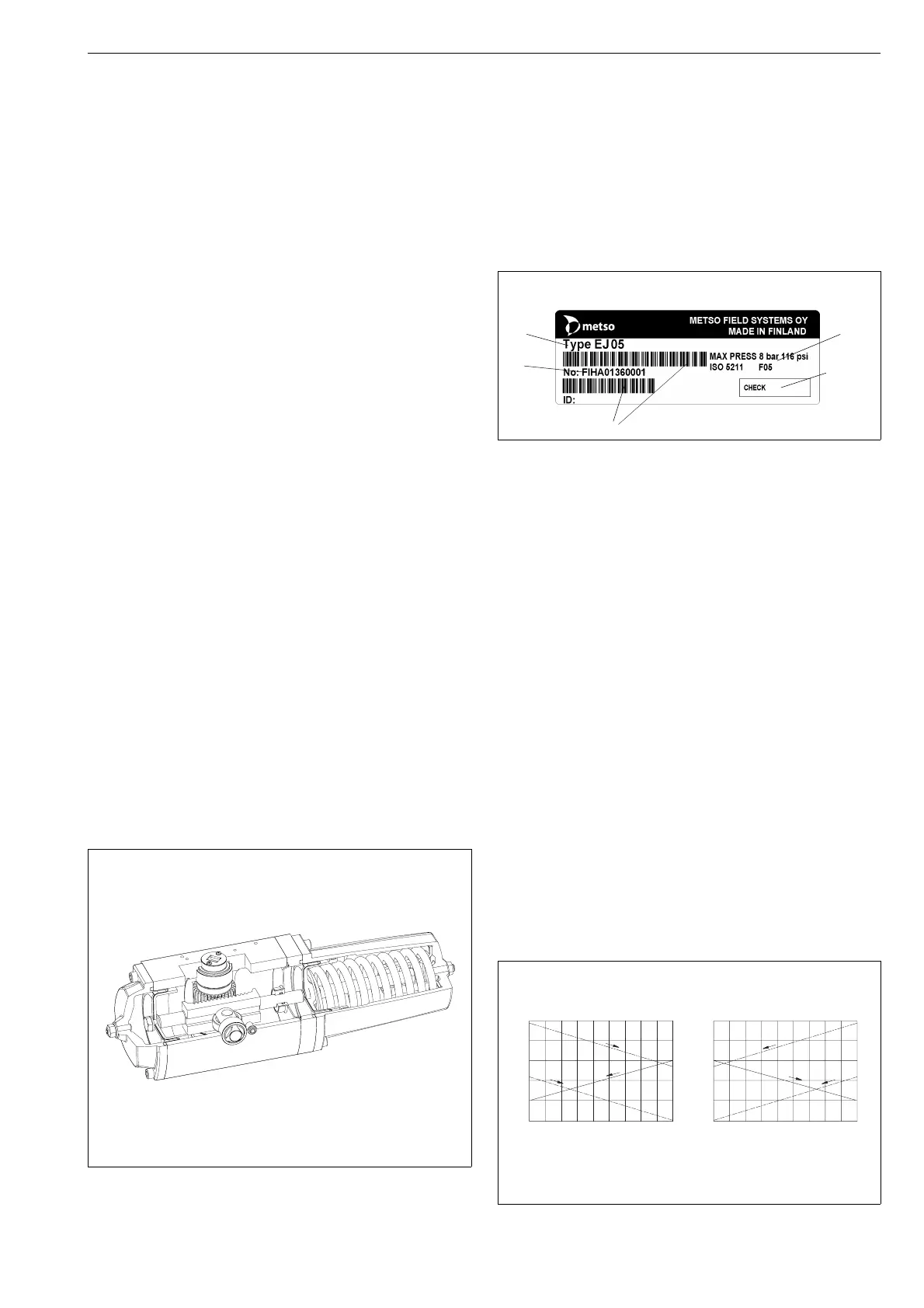
1.3 Actuator labeling.
Attached to the actuator is a label (Figure 2) with the
following information:
1 Type code
2 Place and time of manufacturing and serial number
(yyyy ww nr)
3 Inspected by
4 Maximum supply pressure
5 Bar codes for items 1 and 2
1.4 Technical data.
Operating temperature:
standard design -20 °C to +70 °C
low temperature design -40 °C to +70 °C
high temperature design -20 °C to +120 °C
Maximum supply pressure: 8 bar / 116 psi
Cylinder volume, dm
3
/ in
3
:
EJ 05 0.17 / 10.5
EJ 07 0.4 / 24.5
EJ 10 1.0 / 61.0
EJ 12 2.5 / 152.5
EJ 14 6.0 / 366.0
Nominal torque with standard spring, Nm / lbf ft:
EJ 05 19 / 14
EJ 07 47 / 34.5
EJ 10 117 / 86.5
EJ 12 280 / 206.5
EJ 14 690 / 509
The output torque of the actuator depends directly on the
supply pressure.
The operational direction or turning angle of the actuator
affects the output torque, Figure 3.
Fig. 1. Actuator design
1
4
3
2
5
Fig. 2. ID label markings
1.8
1.6
1.4
1.2
1
Mn
M / Mn
0102030405060708090
angle /
EJ_A
1.8
1.6
1.4
1.2
1
Mn
M / Mn
0102030405060708090
angle /
EJ
M
5 bar
M
4 bar
M
spring
M
5 bar
M
4 bar
M
spring
Fig. 3. The influence of the turning angle on the
torque
3