PICkit
TM
2 User’s Guide
DS51553B-page 8 © 2006 Microchip Technology Inc.
1.5 PICkit™ 2 MICROCONTROLLER PROGRAMMER OVERVIEW
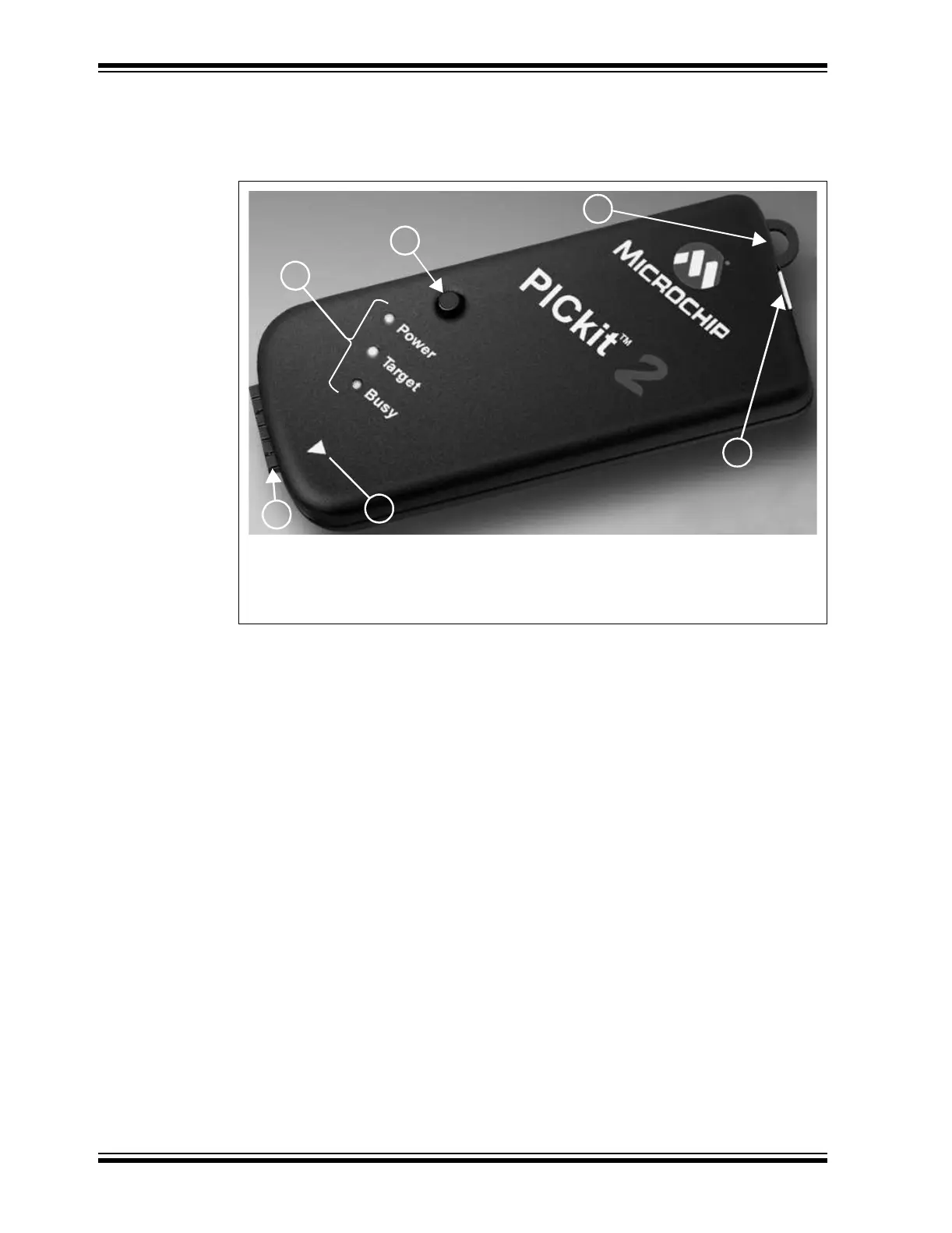
The PICkit™ 2 Microcontroller Programmer overview is shown in Figure 1-1.
FIGURE 1-1: PICkit™ 2 MICROCONTROLLER PROGRAMMER
1.5.1 USB Port Connection
The USB Port Connection is a USB mini-B connector. Connect the PICkit™ 2
Microcontroller Programmer to the PC using the supplied USB cable.
1.5.2 Status LEDs
The Status LEDs indicate the status of the PICkit™ 2 Microcontroller Programmer.
1. Power (green) – Power is applied to the PICkit™ 2 Microcontroller Programmer
via the USB port.
2. Target (yellow) – The PICkit™ 2 Microcontroller Programmer is powering the
target device.
3. Busy (red) – The PICkit™ 2 Microcontroller Programmer is busy with a function
such as Program mode or is alerting that a function is in progress.
1.5.3 Push Button
The push button is for initiating a function that will be implemented in the near future.
1
2
4
3
5
6
Legend:
1 – Status LEDs 3 – Lanyard Connection 5 – Pin 1 Marker
2 – Push Button 4 – USB Port Connection 6 – Programming Connector