PICkit™ 2 User’s Guide
DS51553B-page 38 © 2006 Microchip Technology Inc.
13. Examine the values of the ADCON0 and ADCON1 registers in the Watch
window. The ADCON0 value is ‘0x00’ (b’00000000’). This corresponds to the
hex value designated in the program. However, this is not correct. A review of the
“PIC16F917/916/914/913 Data Sheet” (DS41250), Analog-to-Digital (A/D) Con-
verter Module section, indicates that the last bit should be a ‘1’ (b’00000001’)
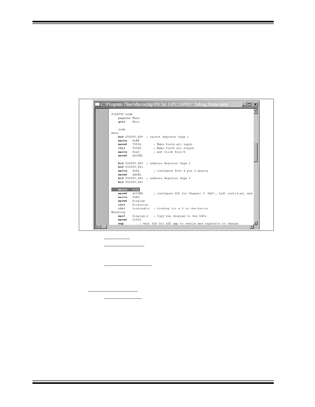
to turn on the A/D module. To fix this bug, change:
“movlw 0x00”
to
“movlw 0x01”, as shown in Figure 4-27.
FIGURE 4-27: A/D MODULE CODE
14. Select File > Save
to save the changes.
15. Select Project > Build All
to rebuild the project. A message will indicate that the
program has been rebuilt. The PICkit 2 Microcontroller Programmer must be
reprogrammed for the changes to take effect.
16. Select Debugger > Program
to reprogram the PICkit 2 Microcontroller Program-
mer with the changes. When the PICkit 2 Microcontroller Programmer dialog
indicates “Programming Succeeded”, the program is ready to run again.
17. Right-click on the line of code that previously had the breakpoint and select
Remove > Breakpoint
.
18. Select Debugger > Run
to run the program in Real-Time mode. Turn the
potentiometer (RA0) to change the value displayed on the LEDs.
The source code in this tutorial contained only one bug. However, real code may have
more. Using the PICkit 2 Microcontroller Programmer and MPLAB IDE debugging
functions, users can successfully find and fix problems in their code.
4.2.11 Programming the Application
When the program is successfully debugged and running, the next step is to program
the PICmicro MCU for stand-alone operation in the finished design. When doing this,
the resources reserved by the ICD are released for use by the application. To program
the application, use the following steps:
1. Disable PICkit 2 Microcontroller Programmer as a debug tool by selecting