PICkit
TM
2 USER’S GUIDE
© 2006 Microchip Technology Inc. DS51553B-page 19
Chapter 3. PICkit™ 2 and ICSP™
3.1 INTRODUCTION
The PICkit™ 2 Microcontroller Programmer can program PICmicro
®
microcontrollers
that are installed in an application circuit using In-Circuit Serial Programming™
(ICSP™). In-Circuit Serial Programming (ICSP) requires five signals:
•V
PP – Programming Voltage; when applied, the device goes into Programming
mode.
• ICSPCLK or PGC – Programming Clock; a unidirectional synchronous serial clock
line from the programmer to the target.
• ICSPDAT or PGD – Programming Data; a bidirectional synchronous serial data line.
•V
DD – Power Supply positive voltage.
•VSS – Power Supply ground reference.
However, the application circuit must be designed to allow all the programming signals
to be connected to the PICmicro device without distorting the programming signals.
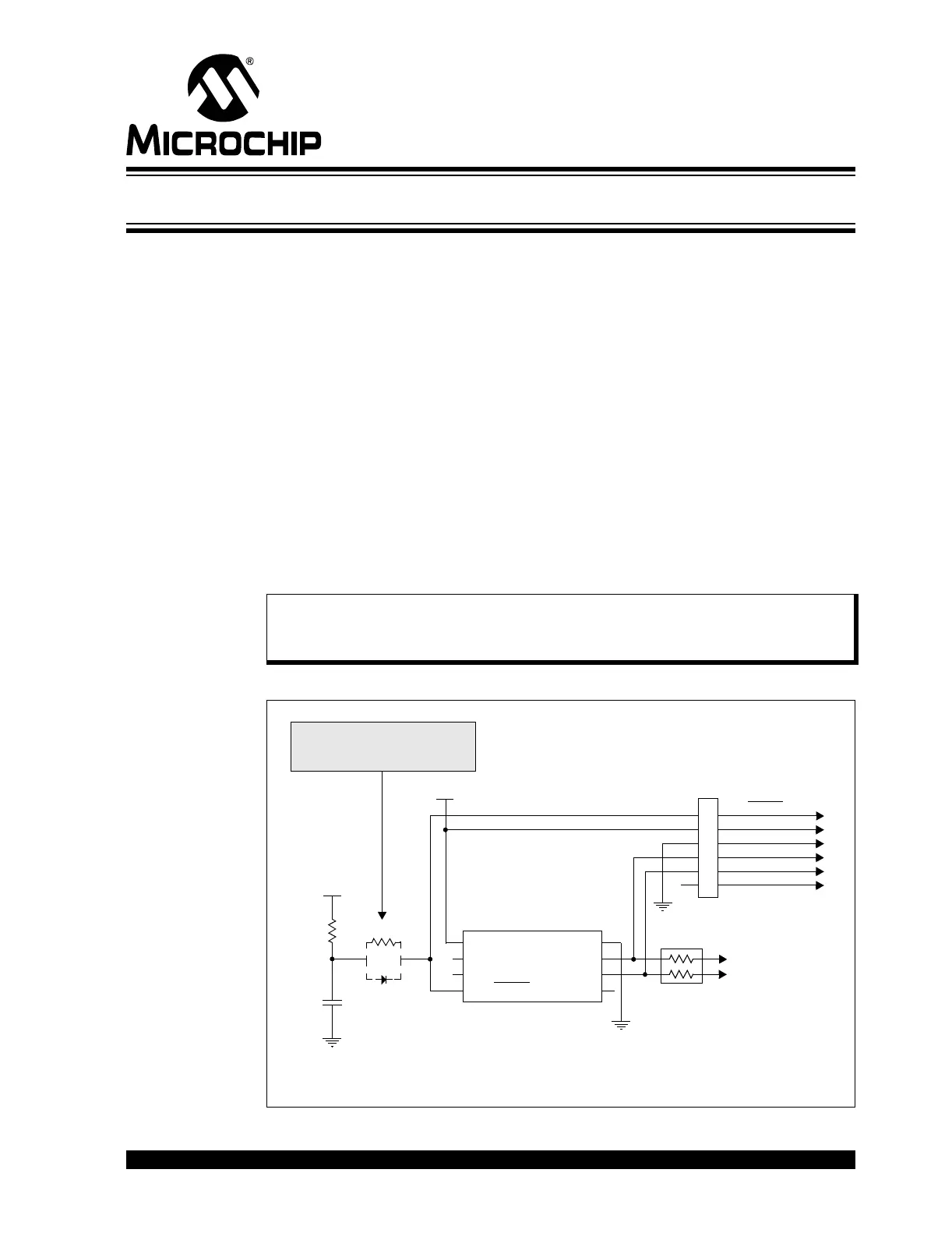
Figure 3-1 shows a typical circuit as a starting point when designing an application
circuit for ICSP. For successful ICSP programming, the precautions in the following
sections need to be followed.
FIGURE 3-1: TYPICAL ICSP™ APPLICATION CIRCUIT
Note: For details on how a specific device is programmed, refer to the device
programming specification available from the Microchip web site at
www.microchip.com.
1
2
3
4
5
6
VPP/MCLR
VDD
VSS
ICSPDAT/PGD
ICSPCLK/PGC
AUX
Target Microcontroller
470 Ohm*
0.1 µF*
1
2
3
4
VDD
RA5
VSS
RA4
RA3/MCLR
/VPP
8
7
6
5
PICkit™ 2
+5V
OR
Device
+5V
To Application
Circuit
Isolation Circuitry:
Resistor or Schottky-type diode
Programming
Header
10k*
* Typical Values
RA0/ICSPDAT
RA1/ICSPCLK
RA2