Terminal Connector Signal Maps
CE-500 MDT Hardware Guide
P
P
i
i
n
n
o
o
u
u
t
t
o
o
f
f
C
C
o
o
n
n
n
n
e
e
c
c
t
t
o
o
r
r
s
s
M
M
a
a
i
i
n
n
T
T
e
e
r
r
m
m
i
i
n
n
a
a
l
l
“
“
C
C
o
o
n
n
1
1
”
”
C
C
o
o
n
n
n
n
e
e
c
c
t
t
o
o
r
r
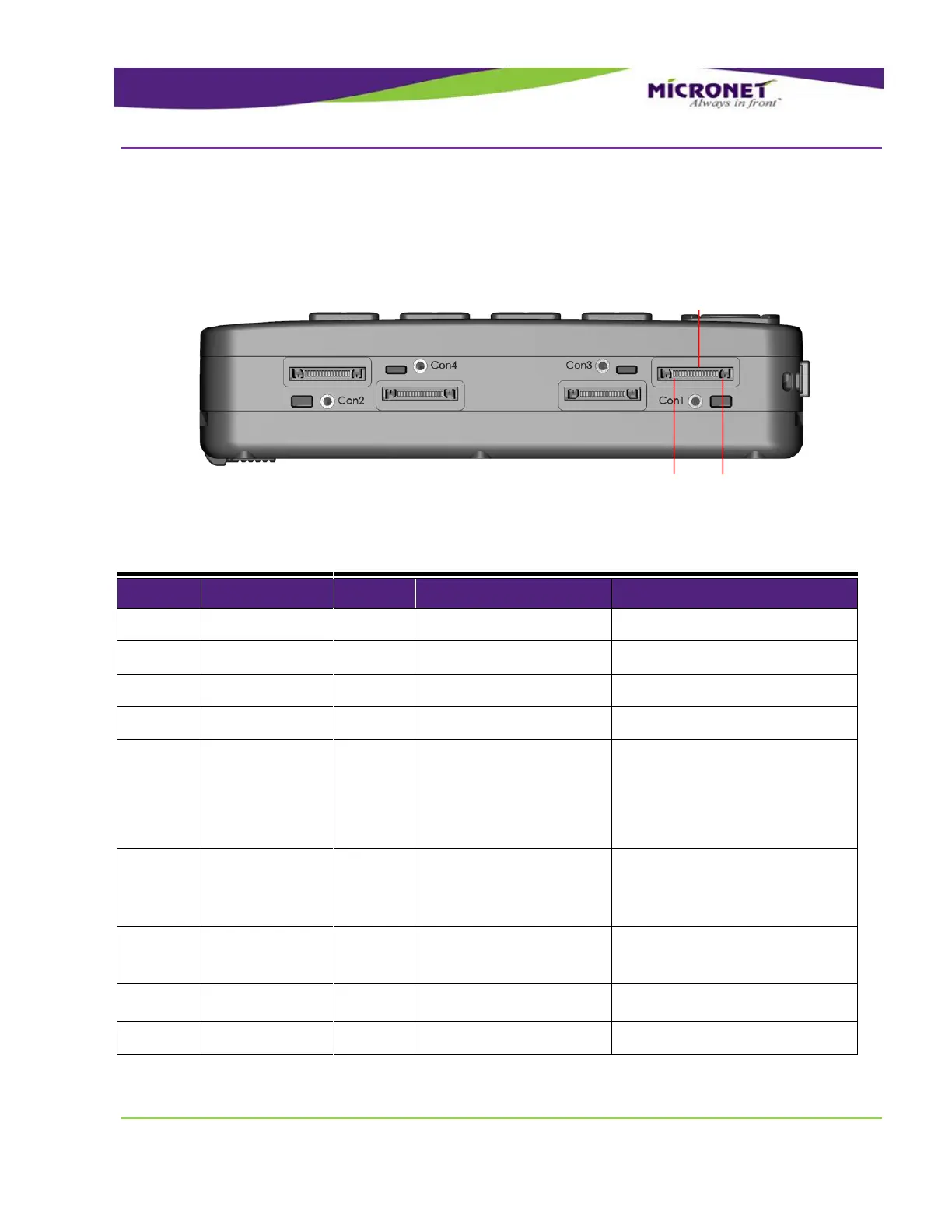
Figure 10 – “Con1” Connector Pinout
Table 4 – Main Terminal “Con1” Connector Signal Map
Digital Input 1 (Ignition
switch)
Typical Min
Max
Input Low: VIL 0V -30V
6V
Input High: VIH 12V-24V +8V
+30V
Open Collector
Max. switchable current = 300mA
Max. switchable voltage = +VIN
Max. saturation voltage = 0.6V
Micronet accessories control
signal
This signal is for Micronet-embedded
accessory-control purposes only.
Do not connect anything to this pin.