CE-500 MDT Hardware Guide
NOTE:
The terminal connectors of the device are located at different rotation angles.
All “shield” pins of the connectors are attached to the ground signal.
B
B
a
a
s
s
i
i
c
c
c
c
r
r
a
a
d
d
l
l
e
e
c
c
o
o
n
n
n
n
e
e
c
c
t
t
o
o
r
r
s
s
+
+
V
V
i
i
n
n
C
C
o
o
n
n
n
n
e
e
c
c
t
t
o
o
r
r
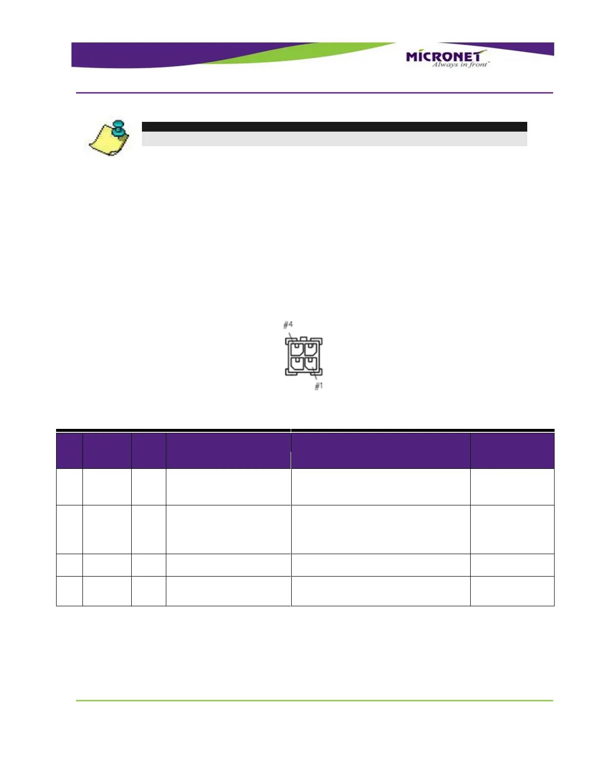
The 12V or 24V and Ground signals of the vehicle-battery as well as the ignition switch signal must be
attached to this connector.
Connector type - Molex Micro-Fit 3.0™ 4 pin plug
Figure 42 – Cradle +Vin Connector Pinout
Table 15 – Cradle +Vin Connector Signal Map
Digital Input 1 (Ignition switch)
Typical Min Max
Input Low: VIL 0V -30V 6V
Input High: VIH 12V-24V +8V +30V
Open Collector
Max. switchable current = 300mA
Max. switchable voltage = +VIN
Max. saturation voltage = 0.6V
Typical Min Max
+12V / 24V +8V +30V
C
C
O
O
M
M
1
1
C
C
o
o
n
n
n
n
e
e
c
c
t
t
o
o
r
r
Connector type - Molex Micro-Fit 3.0™ 6 pin plug