CE-500 MDT Hardware Guide
USB Connector, on page 77
COM2 Connector ,on page 78
Video-in1 connector, on page 80
Microphone connector, on page 81
Left speaker connector, on page 81
M_Control1 Connector, on page 79
Video-in2 connector, on page 80
Audio-out connector, on page 80
Audio-in connector, on page 81
Right speaker connector, on page 81
CAN Bus connector, on page 82
Mounting Arm screw inserts, on page 85
D
D
e
e
v
v
i
i
c
c
e
e
C
C
r
r
a
a
d
d
l
l
e
e
C
C
o
o
n
n
n
n
e
e
c
c
t
t
o
o
r
r
s
s
O
O
v
v
e
e
r
r
v
v
e
e
w
w
Instead of the interfaces that require the standard type of connectors (such as USB and Ethernet), all
other signals are located on the CE-500 Device Cradle by Molex Micro-Fit 3.0™ Plug connector types. To
implement the connectivity, use the opposite (Receptacle) type of connector with the correct amount of
pins for each peripheral interface. This is Molex 43025 Series type of connectors. Use the Molex Micro-
Fit 3.0™ Crimp Terminal Female for wiring. Ensure that the correct wire size (AWG) for each signal is
according to the requirements of the interface-connector Signal Maps specifications.
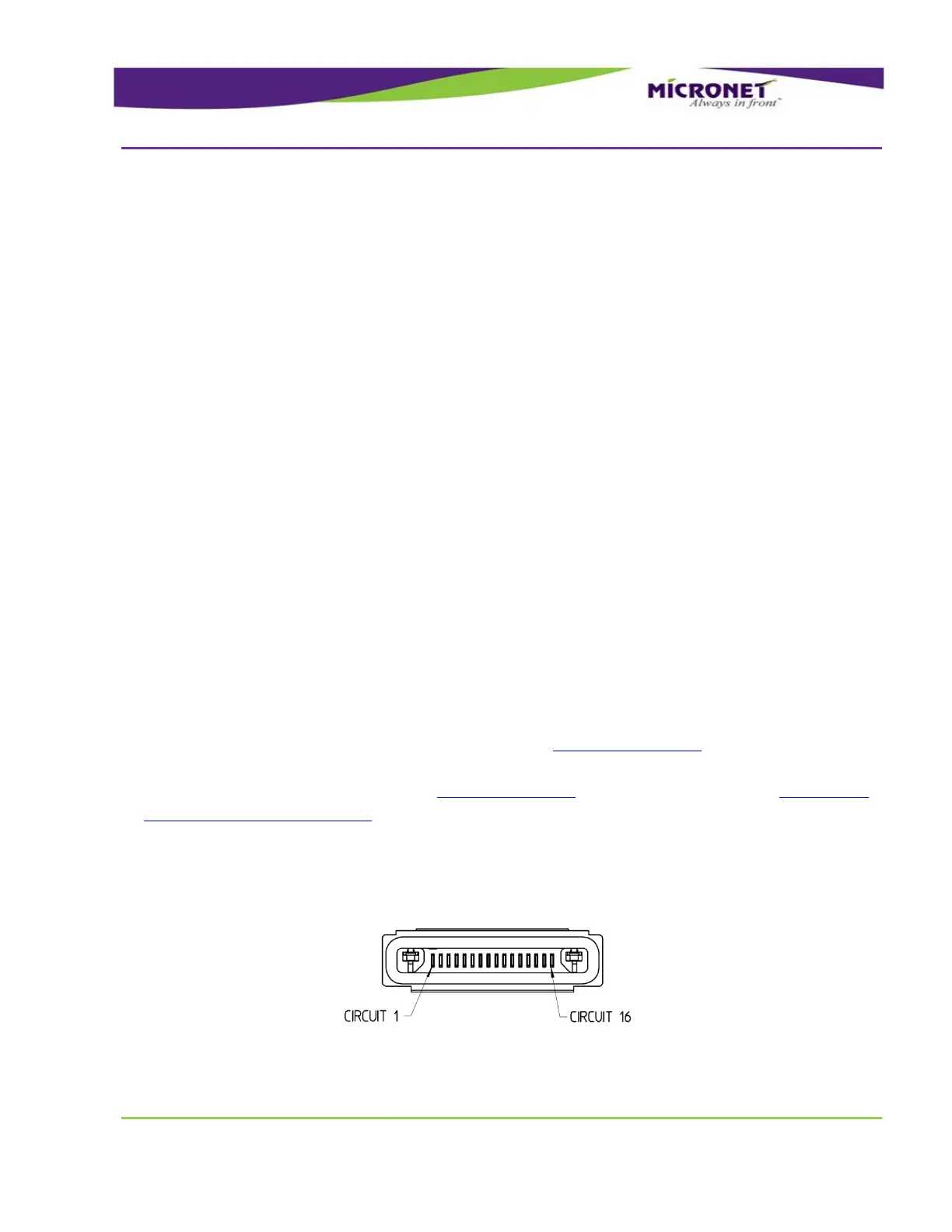
Type of all device connectors of the Cradle - Molex HandyLink™ I/O Interconnect System
Molex part number - 0455931600
Figure 41 – Device Cradle Connector Pinout