Terminal Connector Signal Maps
CE-500 MDT Hardware Guide
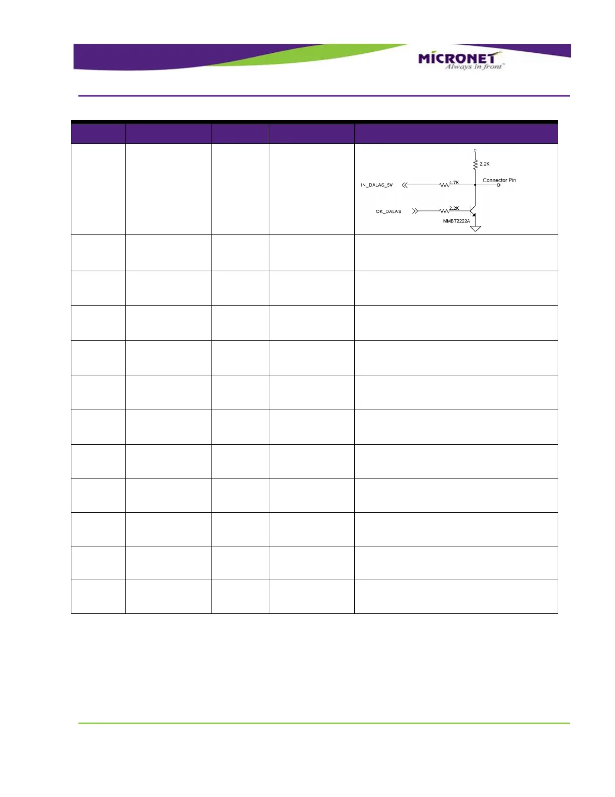
One-Wire
Interface.
(DALLAS ID
Button Interface)
Port
Typical Min Max
Input Low: VIL 0V -30V 6V
Input High: VIH 12V-24V +8V +30V
Micronet
accessories
control signal
This signal is for Micronet embedded
accessories control purposes only.
Do not connect anything to this pin.
Micronet
accessories control
signal
This signal is for Micronet-embedded accessory-
control purposes only.
Do not connect anything to this pin.
Micronet
accessories control
signal
This signal is for Micronet-embedded accessory-
control purposes only.
Do not connect anything to this pin.
Micronet
accessories control
signal
This signal is for Micronet-embedded accessory-
control purposes only.
Do not connect anything to this pin.
Micronet
accessories control
signal
This signal is for Micronet-embedded accessory-
control purposes only.
Do not connect anything to this pin.
Optional – Ethernet
LAN Transmit Data
+
IEEE 802 3/802 3u Standards
Optional – Ethernet
LAN Transmit Data -
IEEE 802 3/802 3u Standards
Optional – Ethernet
LAN Receive Data +
IEEE 802 3/802 3u Standards
Optional – Ethernet
LAN Receive Data -
IEEE 802 3/802 3u Standards