CE-500 MDT Hardware Guide
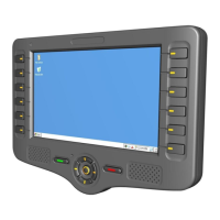
Figure 22 – Terminal Connector Pinout
NOTE:
The device terminal connectors are located at different rotation angles.
All shield pins of the connectors are attached to the Ground signal.
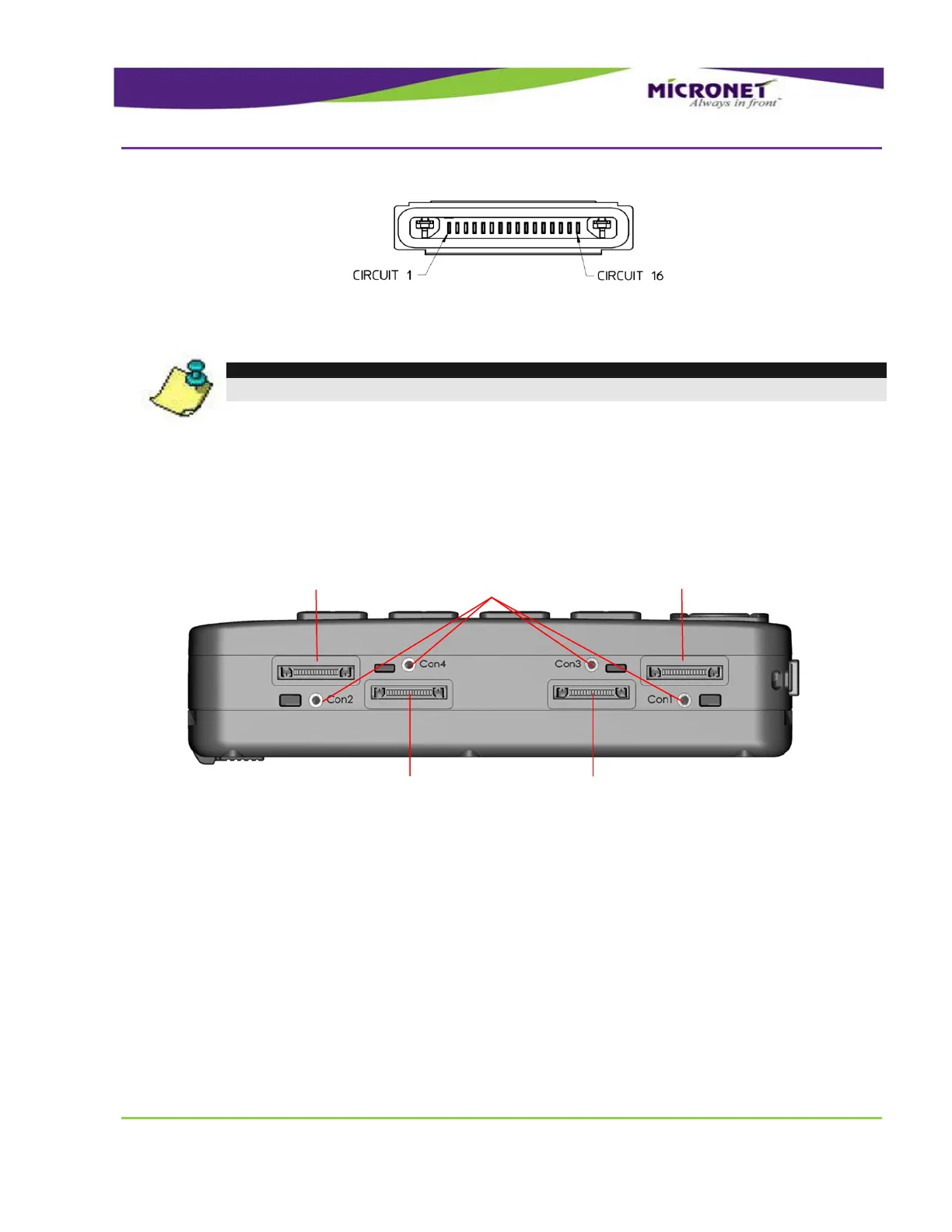
The length of each accessory cable is 1.5 meter.
Figure 23 – Accessory Connectors, Bottom Panel
For more information on CE-500 front panel components, see:
Main Interface Cable, on page 61
Enhanced Interface Cable, on page 65
Video and CANBus Interface Cable, on page 67
Audio Interface Cable, on page 67
Cable mounting screw inserts, on page 59
Video and CANBus Interface
Cable
Cable mounting
screw inserts