EasyManua.ls Logo

MicroNet CE-507 - Page 62

MicroNet CE-507
97 pages
Print Icon
To Next Page IconTo Next Page
To Previous Page IconTo Previous Page
Loading...
Platform Accessories
Accessory Cables
GDUTUG500/01
CE-500 MDT Hardware Guide
62 / 97
Pin
Signal
Function
Wire Size
(AWG) Required
1
TXD1
Transmit Data (COM1)
28
2
RTS1
Request To Send (COM1)
28
3
DGND
Digital Ground
28
4
RXD1
Receive Data (COM1)
28
5
CTS1
Clear To Send (COM1)
28
6
N/C
Not connected
U
U
S
S
B
B
C
C
o
o
n
n
n
n
e
e
c
c
t
t
o
o
r
r
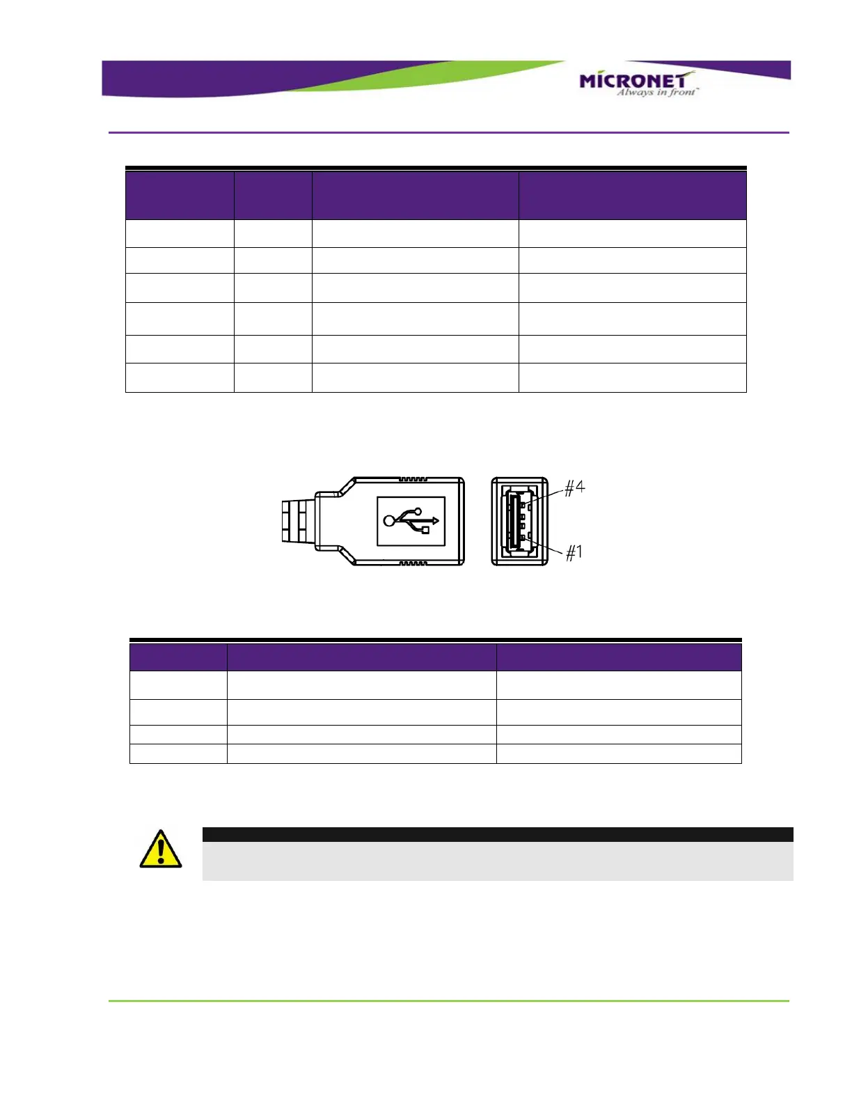
Connector type - USB type-A female
Figure 26 – Main Interface Cable USB Connector Pinout
Table 11 – USB Connector Signal Map
Pin
Signal
Function
1
USB +5V
5V USB Power Out
2
USB D+
USB Data (+)
3
USB D-
USB Data (-)
4
USB GND
USB Ground
P
P
o
o
w
w
e
e
r
r
-
-
A
A
d
d
a
a
p
p
t
t
o
o
r
r
-
-
B
B
o
o
x
x
C
C
o
o
n
n
n
n
e
e
c
c
t
t
o
o
r
r
WARNING!
The Power-Adaptor-Box connector on the main cable interface must be connected only to
the power adaptor box. Do not connect anything else to these signals!

Table of Contents