CE-500 MDT Hardware Guide
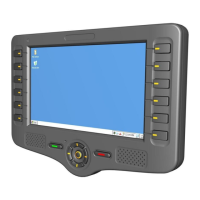
Figure 29 – Power-Adapter-Box to MDT Connector
P
P
o
o
w
w
e
e
r
r
-
-
A
A
d
d
a
a
p
p
t
t
o
o
r
r
-
-
B
B
o
o
x
x
t
t
o
o
+
+
V
V
i
i
n
n
C
C
o
o
n
n
n
n
e
e
c
c
t
t
o
o
r
r
IMPORTANT
The 12V or 24V and Ground signals of the vehicle battery and the ignition switch signal
must be attached to this connector.
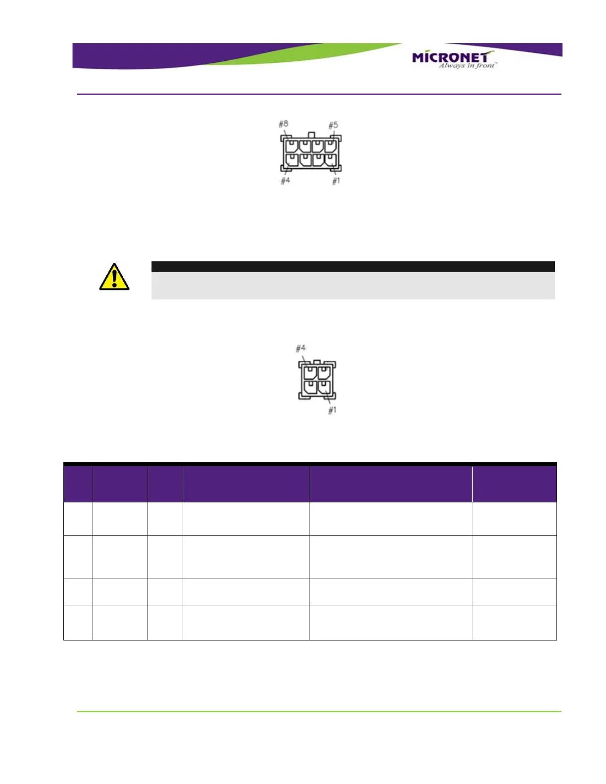
Connector type - Molex Micro-Fit 3.0™ 4 pin plug
Figure 30 – Power-Adapter-Box to MDT Connector Pinout
Table 12 – Power Adaptor Box +Vin Connector Signal Map
Digital Input 1 (Ignition
switch)
Typical Min Max
Input Low: VIL 0V -30V 6V
Input High: VIH 12V-24V +8V +30V
Open Collector
Max. switchable current = 300mA
Max. switchable voltage = +VIN
Max. saturation voltage = 0.6V
Typical Min Max
+12V / 24V +8V +30V