Home
Microscan
Digital Camera
HAWK MV-4000
Page 121 (Access Microscan Rescue Utility)
Microscan HAWK MV-4000 - Access Microscan Rescue Utility
142 pages
Manual
Save Page as PDF
To Next Page
To Next Page
To Previous Page
To Previous Page
Loading...
Access Microscan Rescue Utility
Operating System
Recovery
G
HAWK MV-4000 Smart Camera Guide
G-7
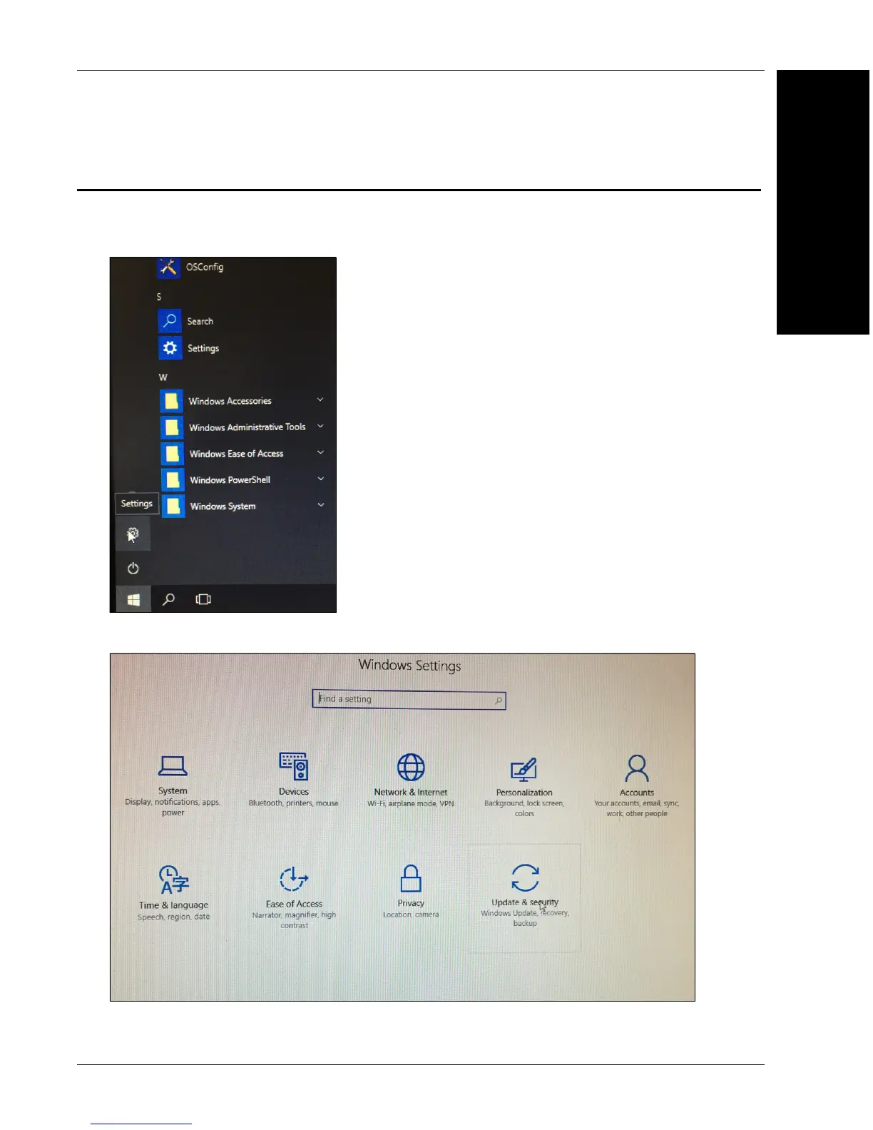
Access Microscan Rescue Utility
If you can boot to Windows:
1.
Select the
Start
button, t
hen choose
Settings
.
2.
Select
Update and Securit
y
.
120
122
Table of Contents
Main Page
Default Chapter
2
Technical Support
2
Fcc Compliance Statement
4
Symbol Description
5
Table of Contents
6
Manual Conventions
8
Preface
8
Purpose of this Manual
8
Welcome
8
CHAPTER 1 Introduction
9
Product Summary
10
Features and Benefits
11
Applications
12
Package Contents
12
HAWK MV-4000 Smart Camera Models
13
HAWK MV-4000 Part Number Structure
14
CHAPTER 2 System Components
15
Hardware Components and Accessories
16
HAWK MV-4000 Dimensions
20
Label Information
24
Mounting, Connecting, and Wiring
25
Connecting to the I/O Interface
31
Input/Output Wiring Using Flying Lead Cable 61-9000151-01
51
Ground and Shield Considerations
52
Electrical and I/O Specifications
54
Environmental Specifications
55
Status Indicators
56
Adding a HAWK MV-4000 to a Network
57
Setting up a Job in Autovision
58
Trigger Debounce
63
Setting up Partial Scan
65
CHAPTER 3 Lighting
67
Illumination
68
External Illumination Control and Wiring
69
Selecting a Lens
71
APPENDIX A Selecting a Lens A-1
72
Lens Selection
72
Lens Specifications
74
Cable Specifications
75
APPENDIX B Cable Specifications B-1
76
61-9000132-01 Cable, Adapter, HAWK MV-4000 to
76
61-9000134-0X Cable, Ethernet, X-Code/Rj45 CAT 6A, 1 M, 3 M, 5 M
77
M12 to Smart Series and Camera Cables
78
97-000012-01 Power Supply, M12 12-Pin Socket, 1.3 M
79
99-000020-02 Trigger, M12 4-Pin Plug, NPN, Dark On, 2 M
80
General Specifications
81
APPENDIX C General Specifications C-1
82
Sensor Board
82
CPU Board
83
VGA/USB Port
84
Electrical Specifications
85
Environmental Specifications
86
Dimensions
87
Digital I/O and Power Adapter Cable Connector
88
100/1000 Base-T Connector
90
VGA/USB Connector
91
Liquid Lens Connector
93
Mvmonitor Web Page
95
APPENDIX D Mvmonitor Web Page D-1
96
Using the Mvmonitor Web Page
96
Cloudlink Web HMI
99
APPENDIX E Cloudlink Web HMI E-1
100
Connecting
100
Application Overview
101
Application Bar
102
Pages, Panels, and Widgets
103
Serial Commands
107
APPENDIX F Serial Commands F-1
115
Operating System Save and Restore
115
APPENDIX G Operating System Save and Restore G-1
116
Restore to Microscan Factory Settings
116
Access Microscan Rescue Utility
121
Back Up/Restore/Capture the os Image with Microscan Rescue Utility
125
OS Config Application
135
APPENDIX H os Config Application H-1
136
Global Settings Tab
136
Write Filter Tab
137
Capture os Tab
138
Languages Tab
139
Emmc Tab
140
EULA Tab
141
Related product manuals
Microscan MicroHAWK MV-20
2 pages