HAWK MV-4000 General Specifications
General
Specifications
C
HAWK MV-4000 Smart Camera Guide C-5
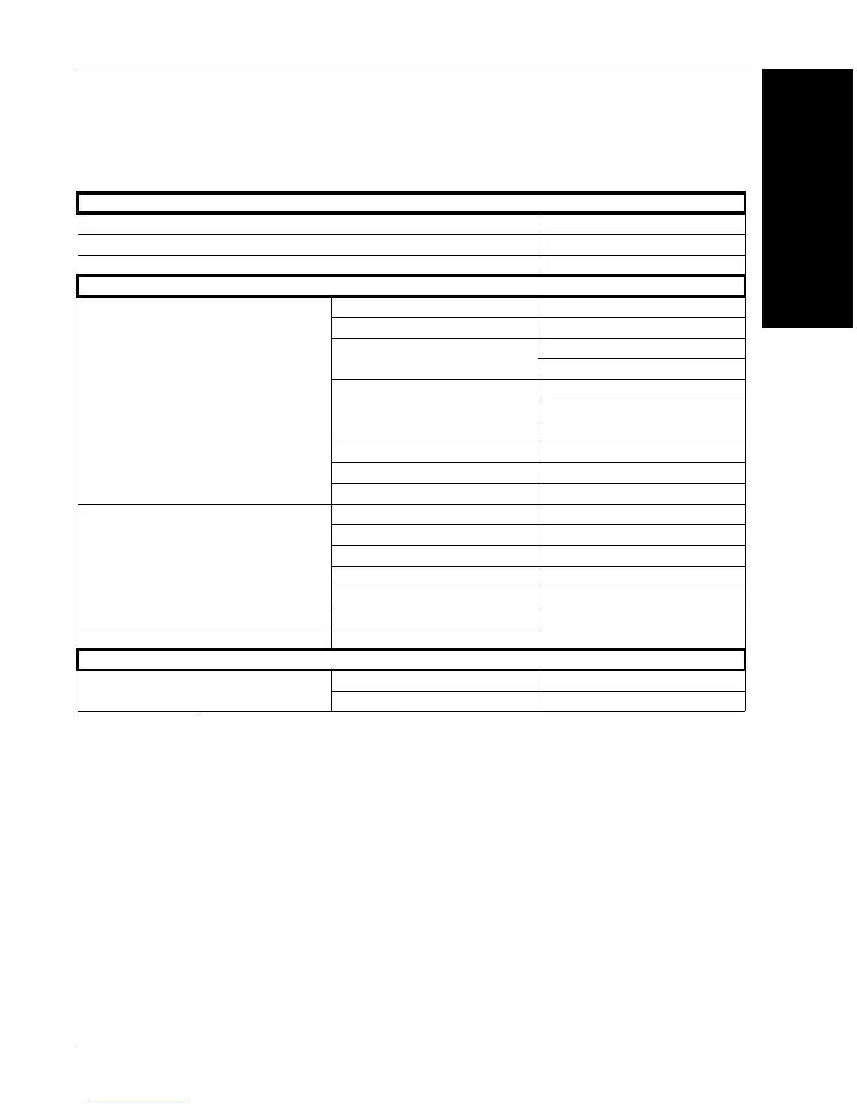
Electrical Specifications
HAWK MV-4000-03, -03C, -13, -13C, -20, -20C, -50, -50C
Operating voltage for the HAWK MV-4000 under testing conditions 24 V
Rated current 600 mA
Operating voltage tolerance ± 10%
I/O Specifications
Optoisolated Output Signals
Operating Voltage 24 V (26 V abs. max.)
Sink Current 50 mA max.
Maximum Leakage Current
1 mA@ 24 V
1 mA@ 26 V
ON Voltage
0.4 V @ 2 mA
1.1 V @ 25 mA
1.5V @ 50 mA
PTC
a
Fuse Max. Time-to-Trip
a. The PTC is an automatically resetting fuse.
1 sec @ 0.5 A
OFF-to-ON Response 2 ms to reach 4 V
b
b. This occurred under the following condition: output pulled to 24 V using 1 kW.
ON-to-OFF Response 50 ms to reach 11 V
c
c. Regardless of whether the signal is sinking or sourcing, this measurement is the same.
Optoisolated Input Signals
Operating Voltage 24 V (26 V abs. max.)
Input Current (Sink or Source) 3.5 mA max.
d
, 1 mA min.
e
d. Maximum input current at max. ON voltage. The connected device must not limit the current to a value
lower than this.
e. Minimum input current at min. ON voltage. Can be used to calculate bleeding resistor needed for 2-wire
proximity sensor.
ON Voltage Level > 11 V
f
f. Recommended > 12 V when using HAWK MV-4000 breakout board.
OFF Voltage Level < 4 V
OFF-to-ON Response 6 ms
ON-to-OFF Response 80 ms
0-10 V Analog Control Output Signal
Non-isolated. Note that the 0-10 V is intended for reference voltage only (< 1 mA).
Varioptic Caspian C-39N0-160-I2C or C-39N0-250-I2C Liquid Lens
Typical
Supplied Voltage 5 V
Rated Current 50 mA