V5 X VRF 50/60Hz
16 201608
Midea V5 X Series Service Manual
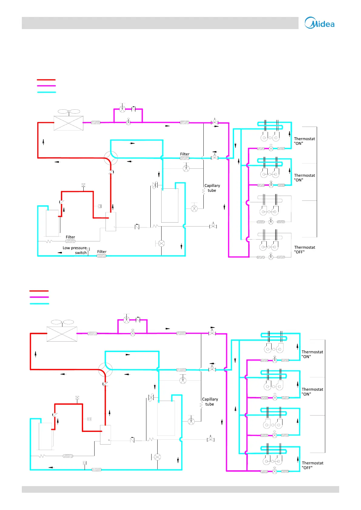
3 Refrigerant Flow Diagrams
MV5-X252W/V2GN1 / MV5-X280W/V2GN1 / MV5-X335W/V2GN1
Cooling operation
Figure 2-3.1: MV5-X252(280, 335)W/V2GN1 refrigerant flow during cooling operation
M
M
M
M
High temperature, high pressure gas
High temperature, high pressure liquid
Low temperature, low pressure
FAN
ON
FAN
ON
FAN
OFF
FAN
ON
Normal control
Filter
Filter
Normal control
Four-way
valve
High pressure sensor
Pressure
regulating
valve
Compressor
Oil
Separator
Accumulator
Solenoid
valve SV2
Electronic expansion valve
closed
High
pressure
switch
Heat exchanger
Heat exchanger
1-way valve
1-way valve
1-way valve
1-way
valve
Filter
Solenoid
valve SV4
Solenoid
valve SV6
Solenoid
valve SV5
Filter
Filter
Filter
Stop valve
Stop valve
Stop valve
Capillary
tube
"ON"
"ON"
"OFF"
"ON"
Indoor unit operation
closed
Oil return operation in cooling mode
Figure 2-3.2: MV5-X252(280, 335)W/V2GN1 refrigerant flow during oil return operation in cooling mode
M
M
M
M
1-way
valve
High temperature, high pressure gas
High temperature, high pressure liquid
Low temperature, low pressure
Heat exchanger
Heat exchanger
High pressure
sensor
Low pressure
switch
Compressor
Pressure
regulating
valve
Oil
Separator
Accumulator
Filter
Filter
Filter
Filter
FAN
ON
Normal control
Normal control
300 steps
Electronic expansion valve
Four-way
valve
Filter
High
pressure
switch
"ON"
"ON"
"OFF"
"ON"
Filter
Stop valve
Indoor unit operation
Filter
Capillary
tube
Stop valve
Stop valve
Solenoid
valve SV2
Solenoid
valve SV4
Solenoid
valve SV6
Solenoid
valve SV5
1-way
valve
1-way
valve
1-way valve
Filter
Filter
FAN
ON
FAN
OFF
FAN
ON
300 steps
 Loading...