V5 X VRF 50/60Hz
201608 45
Part 5 - Diagnosis and Troubleshooting
2.3 Components
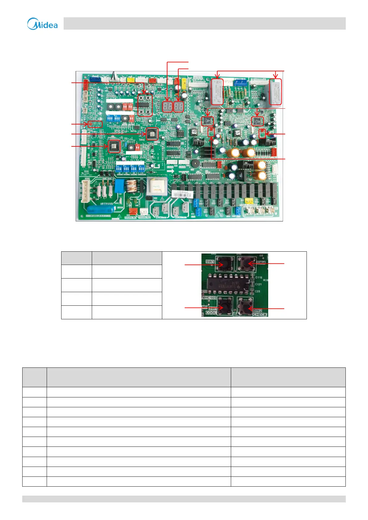
Layout 2.3.1
Figure 5-2.2: Outdoor unit main PCB components
Function of buttons SW1 to SW4 2.3.2
Table 5-2.3: Function of buttons SW1 to SW4
Check for specific errors
SW2 system check button 2.3.3
Before pressing SW2, allow the system to operate steadily for more than an hour. On pressing SW2, the parameters listed
in Table 5-2.4 will be displayed in sequence.
Table 5-2.4: SW2 system check
Parameters displayed on DSP2
Master unit: 0; slave units: 1, 2, 3
Displayed on master unit PCB only
Number of indoor units as set on PCB
Displayed on master unit PCB only
Outdoor unit output metric (total of all units)
Displayed on master unit PCB only
Indoor unit demand metric (total of all units)
Outdoor unit output metric (master unit)
Outdoor unit output metric (this unit)
Table continued on next page …
ENC1
ENC3
S12
S3
S7
S1
ENC2
S4
S2
S5
S6
ENC4
S10
 Loading...