V5 X VRF 50/60Hz
72 201608
Midea V5 X Series Service Manual
xL2 troubleshooting 4.11.8
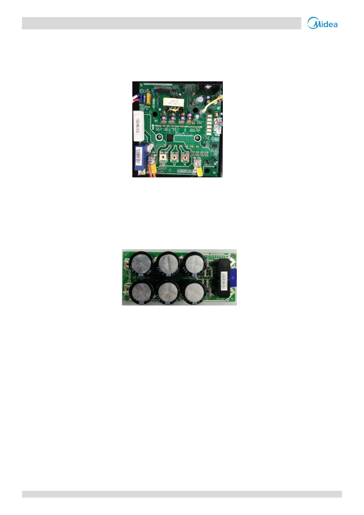
Step 1: Check inverter module
Check the DC voltage between terminals P and N. The normal value is 510-580V, if the voltage is higher than 580V, go
to Step 2.
Figure 5-4.11: Inverter module terminals
Step 2: Check capacitor board
Check the voltage between terminals P and N on the capacitor board. The normal value is 510-580V. If the voltage is
not in the normal range, there is a problem with the electrolytic capacitor power supply. Check the power supply for
high or unstable voltage. If the power supply voltage value is normal, then the main PCB has malfunctioned and
needs to be replaced.
Figure 5-4.12: Capacitor board terminals
xL8/xL9 troubleshooting 4.11.9
Step 1: Check compressor
The normal resistances of the inverter compressor are 0.7-1.5Ω among U V W and infinite between each of U V W
and ground. If any of the resistances differ from these specifications, the compressor has malfunctioned.
Refer to Figures 5-4.6 and 5-4.7 in Part 5, 4.11.6 “xL0 troubleshooting”. If the resistance values are normal, go to Step
2.
Step 2: Check compressor and main PCB
If there is another unit nearby (either in the same system or another system) that is operating normally, its electric
control box can be used to determine whether the xL8/xL9 error is being caused by a compressor fault or a main PCB
fault:
If using another unit in the same system as the unit with the error to perform the test, set it as the master unit
(address 0); if using a unit in another system, use the master unit.
Disconnect the power wires of the compressor referenced in the xL8/xL9 error code.
In the unit that is operating normally, disconnect the power wires that connect a compressor to the electric
control box and use them to connect the compressor with the xL8/xL9 error to the electric control box of the
unit that is operating normally. Ensure that the U, V, W terminals are connected in the right order, and then start
the system that is operating normally.
If the compressor with the xL8/xL9 error runs normally, replace the main PCB of the unit with the xL8/xL9 error
 Loading...