V5 X VRF 50/60Hz
201608 97
Part 5 - Diagnosis and Troubleshooting
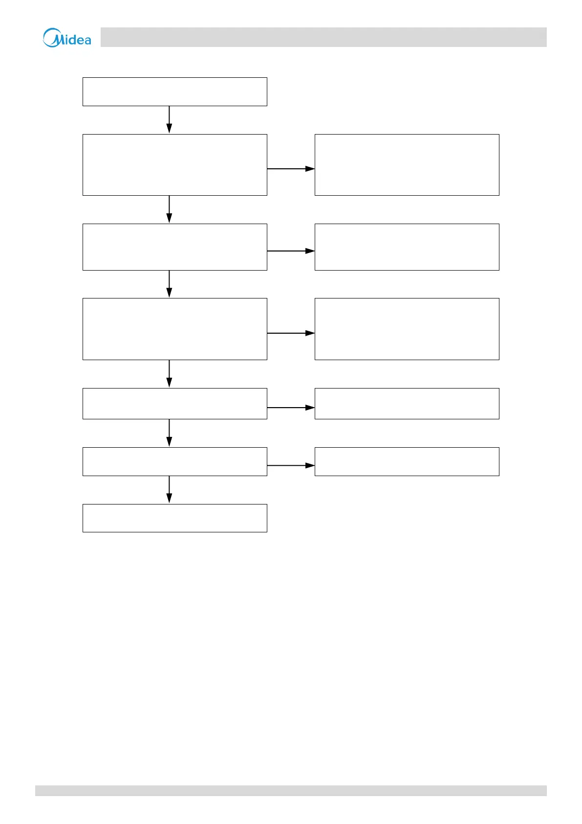
Procedure 4.22.4
Compressor top temperature sensor
and/or discharge pipe temperature
sensor connections on main PCB are
loose
1
Ensure the sensors are connected
properly
Compressor top temperature sensor
and/or discharge pipe temperature
sensor have short circuited or failed
2
Replace the faulty sensor(s)
Poor heat insulation of compressor top
temperature sensor resulting in
temperature reading lower than actual
temperature
Ensure sufficient heat insulation for
compressor top temperature senor
Discharge part of the refrigerant. Add oil
if it leaks during discharge
Discharge pressure is too high
Troubleshoot as for a P1 error
4
Notes:
1. Compressor top temperature sensor and discharge pipe temperature sensor connections are ports CN10 and CN11 on the main PCB (labeled 1 and 2,
respectively, in Figure 5-2.1 in Part 5, 2.2 “Ports”).
2. Measure sensor resistance. If the resistance is too low, the sensor has short-circuited. If the resistance is not consistent with the sensor’s resistance
characteristics table, the sensor has failed. Refer to Part 2, 1 “Layout of Functional Components” and to Table 5-5.2 in Part 5, 5.1 “Temperature Sensor
Resistance Characteristics”.
3. To check for excess refrigerant:
Re-start the outdoor units. If an R1 or R2 error is displayed upon start-up, there is excess refrigerant in the system.
Excess refrigerant causes discharge temperature to be lower than normal, discharge pressure to be higher than normal and suction pressure to be
higher than normal. For normal system parameters refer to Tables 5-5.4 and 5-5.5 in Part 5, 5.2 “Normal Operating Parameters of Refrigerant
System”.
4. See Part 5, 4.16 “P1 Troubleshooting”.
 Loading...