V5 X VRF 50/60Hz
201608 55
Part 5 - Diagnosis and Troubleshooting
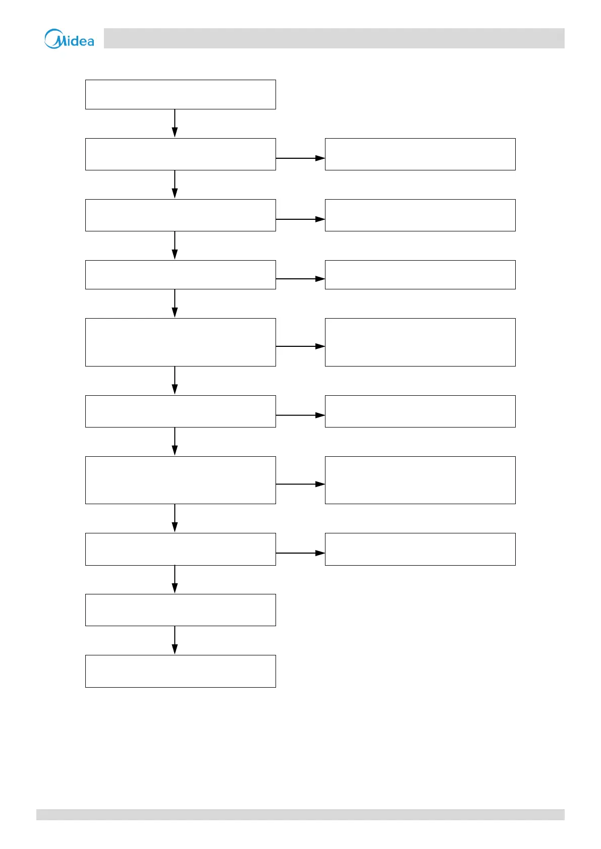
Procedure 4.4.4
Communication wires P Q E have short
circuited or disconnected
1
Reconnect the communication wires
Communication wires P Q E are not
connected in a daisy chain
2
Connect the communication wires in a
daisy chain
IDU power supply is abnormal
Ensure normal power supply
Wires between outdoor main PCB and
electric control box communication
terminals block are loose
3
Ensure the wires are connected properly
Interference from high voltage (220V or
higher) wires
4
Ensure the communication wires and
high voltage wires are separated
Communication wires are close to a
source of electromagnetic radiation such
as transformer or strong fluorescent lamp
Remove the source of interference, or
add additional shielding to the
communication wires
The length of communication wire is over
1200m
Reduce the wire length to less than
1200m or strengthen the signal
Replacing outdoor main PCB resolves the
error
Replace electric control box
communication terminals block
5
Notes:
1. Measure the resistance among P, Q and E. The normal resistance between P and Q is 120Ω, between P and E is infinite, between Q and E is infinite. Refer
to Figures 5-1.2 and 5-1.4 in Part 5, 1 “Outdoor Unit Electric Control Box Layout” and to the V5 X Engineering Data Book, Part 3, 9.3 “Communication
Wiring”.
2. Refer to the V5 X Engineering Data Book, Part 3, 9.3 “Communication Wiring”.
3. Refer to Figures 5-1.2 and 5-1.4 in Part 5, 1 “Outdoor Unit Electric Control Box Layout” and to the V5 X Engineering Data Book, Part 2, 5 “Wiring Diagrams”.
4. Refer to the V5 X Engineering Data Book, Part 3, 9.1 “General” for required separation distances between communication wiring and power wiring.
5. Refer to Figures 5-1.2 and 5-1.4 in Part 5, 1 “Outdoor Unit Electric Control Box Layout”.
 Loading...