V5 X VRF 50/60Hz
201608 37
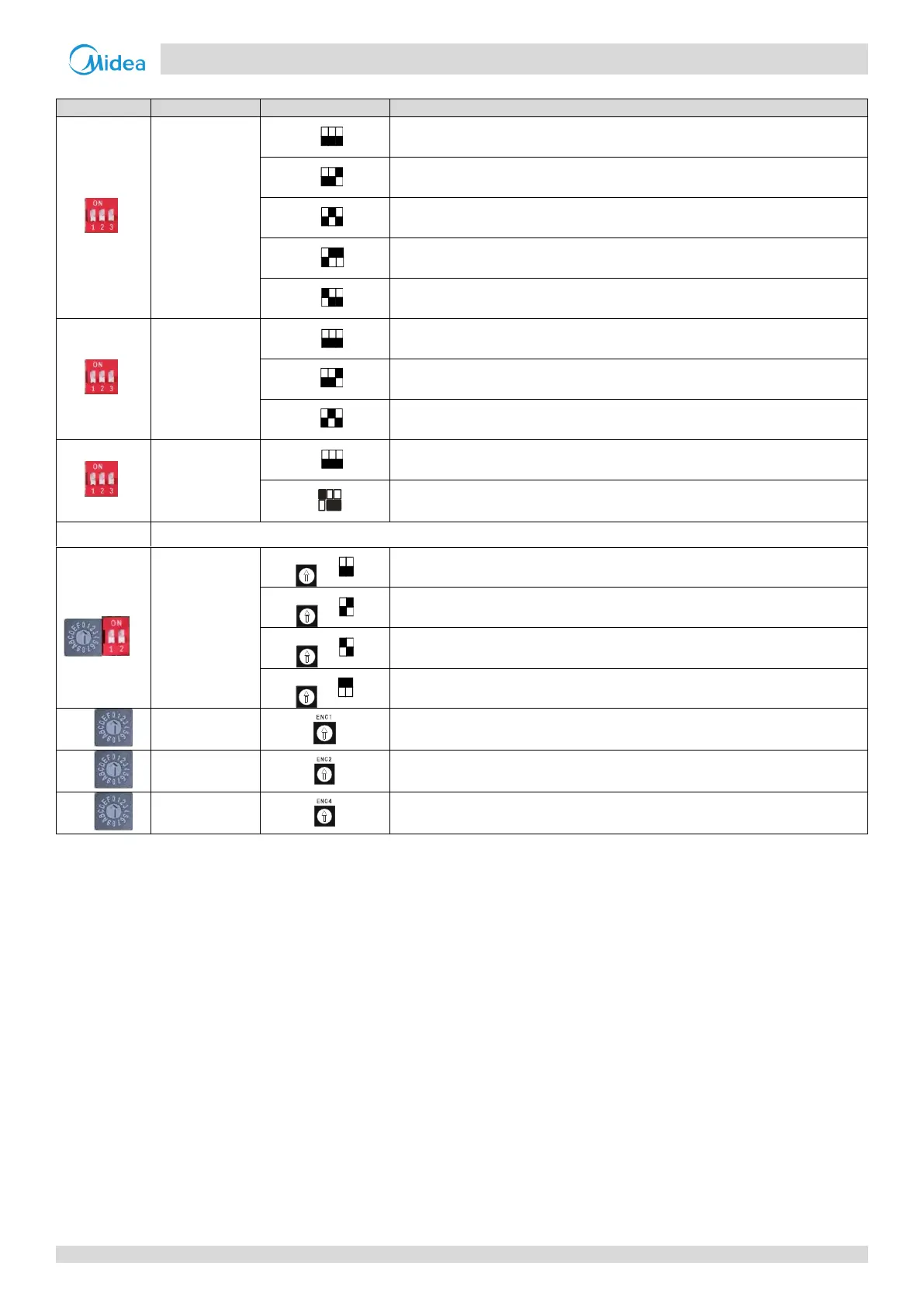
Table 4-1.1: Outdoor unit main PCB switch settings (continued)
Heating priority (default)
VIP priority or voting priority
Manual addressing (default)
Clear indoor unit addresses
Number of
indoor units
manually set
The number of indoor units is not manually set (default)
The number of indoor units is manually set on switches ENC3 and S12
The number of indoor units is in the range 0-15
0-9 on ENC3 indicate 0-9 indoor units; A-F on ENC3 indicate 10-15 indoor units
The number of indoor units is in the range 16-31
0-9 on ENC3 indicate 16-25 indoor units; A-F on ENC3 indicate 26-31 indoor units
The number of indoor units is in the range 32-47
0-9 on ENC3 indicate 32-41 indoor units; A-F on ENC3 indicate 42-47 indoor units
The number of indoor units is in the range 48-63
0-9 on ENC3 indicate 48-57 indoor units; A-F on ENC3 indicate 58-63 indoor units
Only 0, 1, 2, 3 should be selected
0 is for master unit; 1, 2, 3 are for slave units
Only 0, 1, 2, 3, 4, 5, 6, 7 should be selected
0: 8HP; 1: 10HP; 2: 12HP; 3: 14HP; 4: 16HP; 5: 18HP; 6: 20HP; 7: 22HP
Only 0, 1, 2, 3, 4, 5, 6, 7 should be selected
Notes:
1. Black denotes the switch position.
3. Refer to Part 4, 1.2.2 “Priority mode setting”.
4. Refer to Part 4, 1.2.3 “Addressing mode setting”.
5. Switch ENC2 is factory-set and its setting should not be changed.
 Loading...