SECTION V
SCHEMATICS AND DIAGRAMS
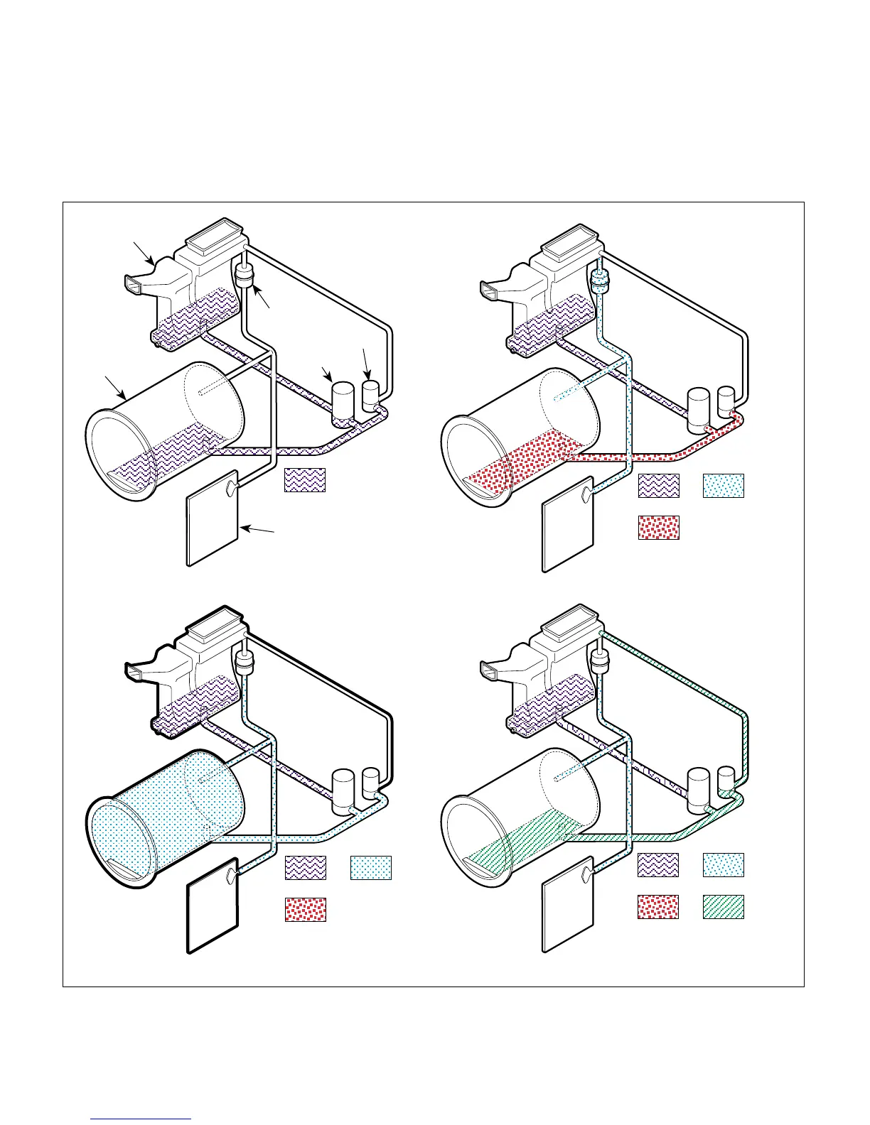
Figure 5-5. Flow Diagram
© Midmark Corporation 2002 SF-1827 Page 5-11 Printed in U.S.A.
Water
Water
Heated
Water
Water
Heated
Water
Steam
Water
Heated
Water
Steam
Vented
Steam/Water
PHASE 1 (Filling) PHASE 2 (Heat-Up)
PHASE 3 (Sterilizing) PHASE 4 (Vent)
Steam/Air
Condensing
Tank / Reservoir
Pressure
Vessel
Control
PC
Board
Bellows
Fill
Solenoid
Vent
Solenoid
MA207902
5.2 Flow Diagram
Figure 5-5 illustrates the water, heated water, steam,
and vented steam/water flow throughout the sterilizer
during a cycle.