Preva Installation/Service Manual, 00-02-1577, Revision E01
18
Wood Stud
Wall, Solid
Wall, or
Reinforced
Wood
Cabinet
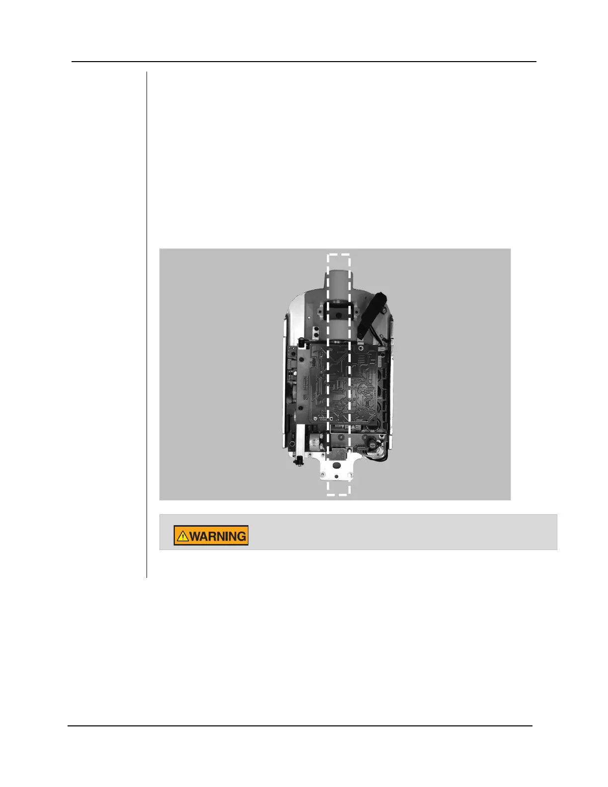
The Control Unit should be located at a height of 39 inches [99 cm] from the floor to the
bottom of the control, mounted on the wood stud, as shown in Figure 9. The large range of
travel of the Articulating Arm provides some flexibility in the vertical position. Two mounting
holes are provided. Refer to the supplied mounting template, shown in Figure 8, for
specific locations.
In order to mount to a solid, masonry type wall, the same mounting holes and mounting
template as the single wood wall stud are used. The installer must supply appropriate
fasteners.
The power supply 2x4 junction box should be mounted to the left of the mounting stud at
the appropriate height, as indicated in the mounting template.
Note: A 4x4 junction box will not be covered by the Control Unit. Refer to the supplied
mounting template for specific location.
Figure 9
Wood Wall
Stud Mount
Do not attach the 208 cm (82 in.) reach system to a wall in the single
stud configuration. Contact Midmark Technical Support for guidance.