Preva Installation/Service Manual, 00-02-1577, Revision E01
41
Line Power,
Permanently
Wired
Installation
1. Using a 3 mm Allen wrench, remove the power line terminal strip cover at the base
of the Power Supply Control Board to gain access to the power line terminal strip,
as shown in
Figure 30.
2. Attach the hot (black) wire of the mains to the connection identified as LINE on the
power strip.
3. Attach the neutral (white) wire of the mains to the connection identified as NEUT
on the power strip.
4. Attach the ground (green) wire of the mains to the connection identified as GND
on the power strip.
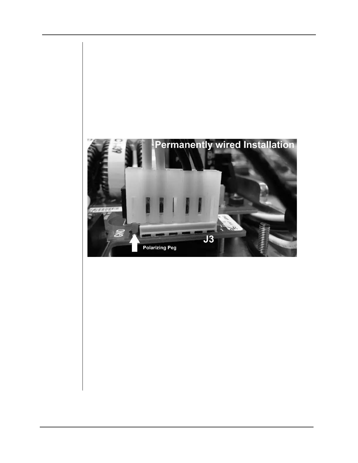
5. The connector from the power switch harness at J3 of the Power Supply Control
Board should be left in the default position as shown in Figure 27.
6. Leave the power line terminal strip cover off until the following electrical
verification procedure is complete.
Figure 27
Power Switch
Harness
Configuration
for
Permanently
Wired
Installation
Line Power,
Cord-
Connected
Installation
1. Using a 3 mm Allen wrench, remove the power line terminal strip cover at the base
of the Power Supply Control Board to gain access to the power line terminal strip,
as shown in
Figure 30.
2. Connect the flanged spade lug of the hot (black) wire of the power cord to the
connection identified as LINE on the power strip.
3. Connect the flanged spade lug of the neutral (white) wire of the power cord to the
connection identified as NEUT on the power strip.
4. Connect the flanged spade lug of the ground (green) wire of the power cord to the
connection identified as GND on the power strip.
5. Remove the connector from the power switch harness at J3 of the Power Supply
Control Board.
6. Remove the Polarizing Peg from position 7 of the connector. Use a needle nose
plier to rotate the polarizing peg 45 degrees and pull to remove it.
7. Insert the polarizing peg into position 1 of the connector.
8. Reconnect the connector to J3 of the Power Supply Control Board. Align the
polarizing peg as shown in Figure 28.
9. Attach the bracket and strain relief as shown in Figure 29.
10. Leave the power line terminal strip cover off until the following electrical
verification procedure is complete.