Preva Installation/Service Manual, 00-02-1577, Revision E01
86
Produced
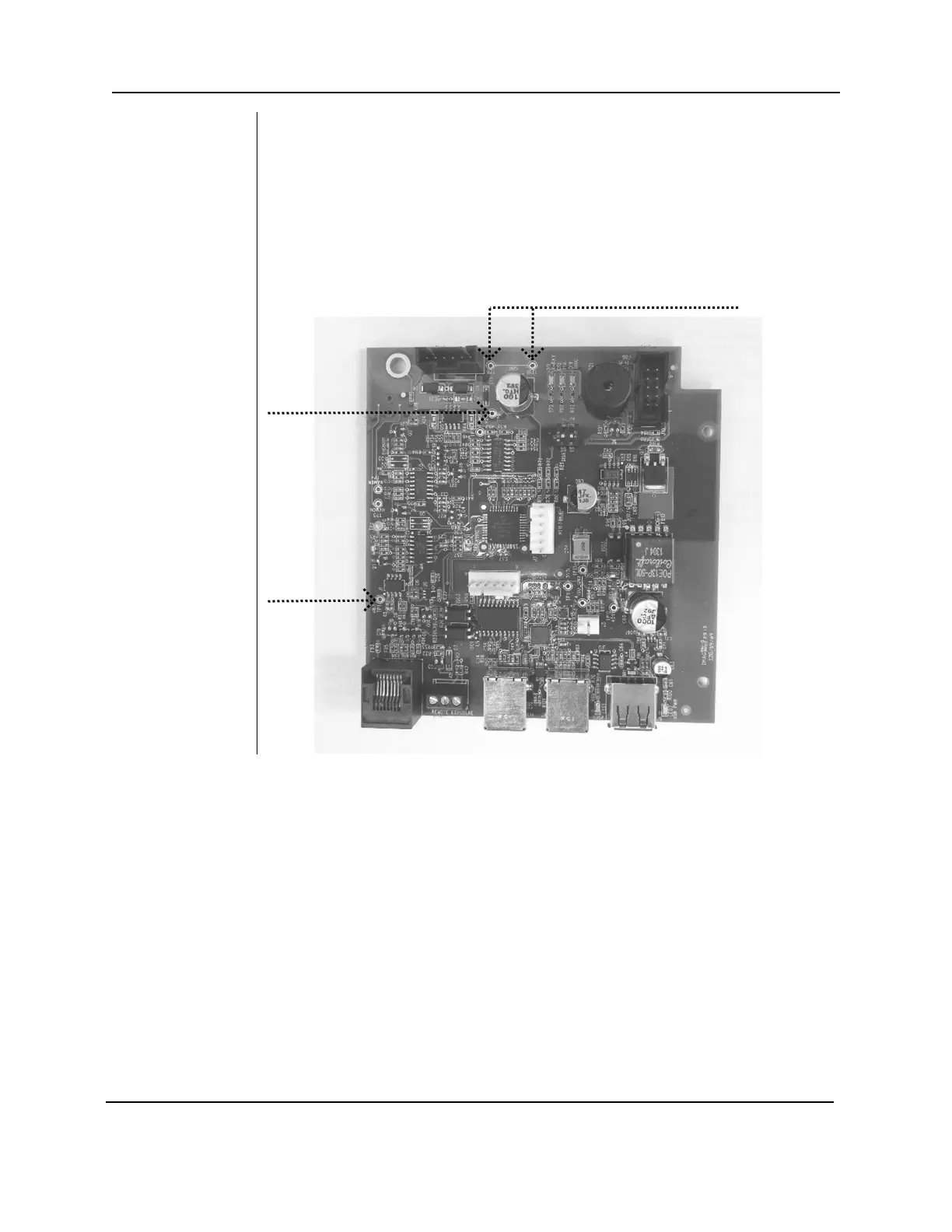
1. On the Logic Board, measure voltages at TP1 (+8.1V) and TP9 (+24V). Use
TP8 or TP10 as Common Return. If any of these voltages are not present
after power is applied, next check voltages on the Power Supply Board.
2. On the Power Supply Board, Figure 63, use TP2 as a common test point to
check TP1 +24 volts DC and TP3 8.1 volts DC. Then, use TP5 as the
common return to check TP4 for the presence of +12 volts DC, as shown in
Figure 62
. Should any of these voltages not be present, replace the Power
Figure 62
Logic Board
30-08160
Use TP8 or TP10 for Common Return when
measuring DC voltages.