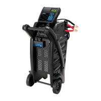
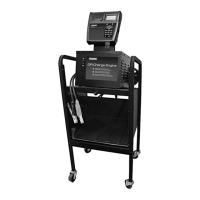
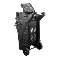
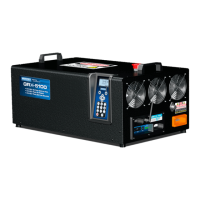
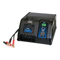
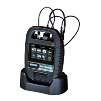
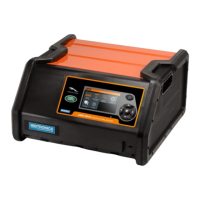
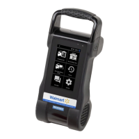
GR8-1200 OEM
Midtronics Inc. 7000 Monroe Street Willowbrook, IL 60527
www.midtronics.com
21
Inspecting the Battery
Before starting the test visually inspect the battery for:
• Cracked, buckled, or leaking case. If you see any of these
defects, replace the battery.
• Corroded, loose, or damaged cables and connections. Re-
pair or replace them as needed.
• Corrosion on the battery terminals, and dirt or acid on the
case top. Clean the case and terminals using a wire brush
and a mixture of water and baking soda.
• Low electrolyte level. If the electrolyte level is too low, add
distilled water to ll up to 1/2 above the top of the plates
and fully charge the battery. Do not over ll.
• Corroded or loose battery tray and hold-down xture.
Tighten or replace as needed.
Testing Out-of-Vehicle (Battery Test)
The preferred battery test location is in the vehicle. However, if
you plan to test out of the vehicle:
• Always disconnect the negative cable from the battery
rst and reconnect it last.
• Always use a carry tool or strap to lift and transport the
battery.
CAUTION: When testing side-post or Group 31
batteries, always use lead terminal adapters pro-
vided with the GR8—do not test at the battery’s
steel bolts. To avoid damage, never use a wrench
to tighten the adapters more than 1/4 turn. Fail-
ure to properly install lead terminal adapters, or
using adapters that are dirty or worn, may cause
false test results.
Testing In-Vehicle (System Test)
Before starting the test, inspect the alternator drive belt. A belt
that is glazed or worn, or lacks the proper tension, will prevent
the engine from achieving the rpm levels needed for the test.
The preferred test position is at the battery posts. If you must
test at a remote-post location, it should have both a positive
and negative post. Otherwise, you must remove the battery
and perform a System Test.
At the start of the test, place the vehicle transmission in PARK,
make sure all vehicle accessory loads are o , the key is not in
the ignition, and the doors are closed.
Connecting to the Battery
Connect the charging clamps to the battery in accordance
with all precautions and safety instructions. Do not connect
either clamp to the vehicle’s chassis.
Connect the red clamp to the positive (+) terminal and the
black clamp to the negative (–) terminal.
If you connect the clamps in the wrong polarity (red to
negative or black to positive), the analyzer sounds an alarm
and displays CLAMPS REVERSED! Reconnect the clamps.
To make sure both sides of the clamps are gripping
the terminals, rock the each clamp back and forth.
A poor connection will prevent testing, and the analyzer
displays the message CHECK CONNECTION. If the message
reappears after you have correctly reconnected the clamps,
clean the terminals and reconnect.
Connecting to AC Power
Plug the charger into a dedicated, grounded nominal 15-amp
or higher AC outlet. Press the power switch to the ON position.
Chapter 4: Test Preparation
Chapter 4: Test Preparation