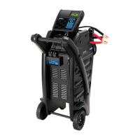
GR8-1200 OEM
Midtronics Inc. 7000 Monroe Street Willowbrook, IL 60527
www.midtronics.com
40
Chapter 13: Cable Drop Test
Cable Drop Test
If the test results for the starter or charging systems indicate
that there may be a problem, you may want to perform the
Cable Drop Test to determine if it is due to worn cables or bad
connections between the battery and the alternator or starter.
Worn cables or bad connections create higher resistance,
which causes a voltage drop across the circuit. The voltage
drop reduces current carrying capability that displays the
same symptoms as a weak alternator or starter and causes
premature battery failure.
There’s no need to run the engine. The Cable Drop Test uses
Midtronics’ conductance technology to send a signal through
the circuit at the component under test. The GR8 then
simultaneously calculates voltage drop on the positive (+)
and negative (–) sides of any circuit as well as the total voltage
drop. The amperage range for each of the four tests is 0 to
1000 A. When you change the setting from the factory defaults,
the GR8 will store your setting in memory for your next test.
There are three preset tests:
• BATTERY GROUND
• STARTER CIRCUIT
• ALTERNATOR CIRCUIT
A fourth test, OTHER CIRCUIT, tests other grounds and circuits
against your speci ed amperage capacity.
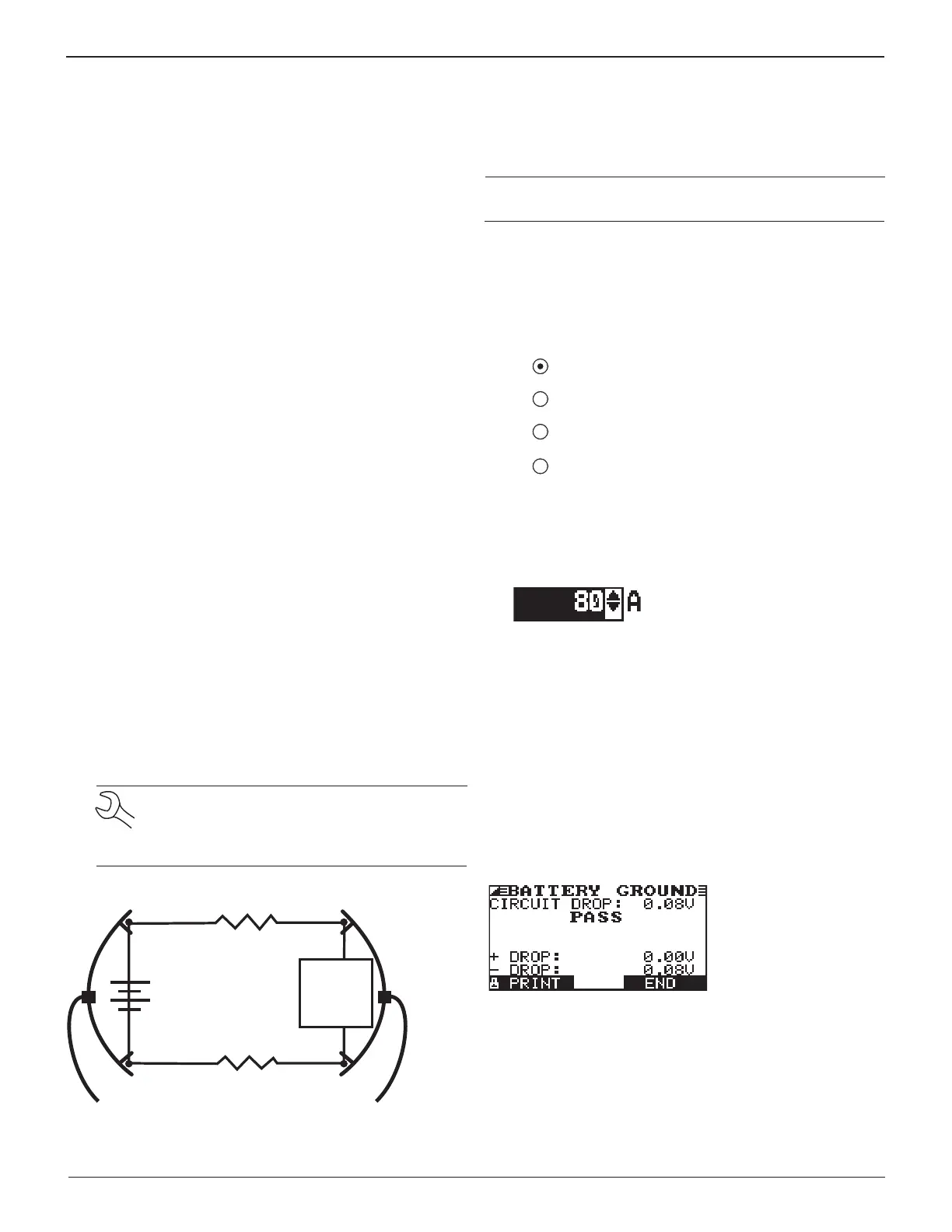
The test requires two test lead connections, as shown in the
gure below.
• Battery test leads at the component’s output lead (the B+
or output screw on the alternator) and the component’s
housing as ground
• DMM test leads at the battery terminals
NOTE: The test requires a complete circuit. If
you’re testing a system with a remote solenoid,
you can test from the battery to the solenoid, but
not from the battery to the starter.
R
Battery
Battery Test Lead
DMM Test Lead
Component
Under
Test
1
R
2
+
–
Red Red
Black Black
To begin, select the Cable Drop Test icon in the Main Menu and
follow the instructions on the display.
IMPORTANT: For accurate results the battery should be good
and fully charged before you perform a test.
Battery Ground Test
The Battery Ground Test measures the voltage drop for the
ground strap.
1. SELECT CIRCUIT: Use the UP/DOWN ARROWS or the nu-
merical keypad to select the Battery Ground Test.
1 BATTERY GROUND
2 STARTER CIRCUIT
3 ALT CIRCUIT
4 OTHER
Press the NEXT soft key to continue.
2. SET AMPS: Use the UP/DOWN ARROWS or the keypad to
select the rated amperage of the circuit you are testing.
The default is 80 A.
Press the NEXT soft key to continue.
3. Connect the main clamps (battery test leads) to the bat-
tery and ground: positive (+) clamp to the battery’s posi-
tive post; negative (–) clamp to the vehicle chassis.
4. Connect the DMM cable to the battery posts: positive (+)
clamp to the positive post; negative clamp (–) to the nega-
tive post.
For the next few seconds the GR8 will display the word TESTING
and a stopwatch while it evaluates the battery ground.
Battery Ground Test Results
If there is a problem, the decision is CLEAN AND RETEST OR
REPLACE. To print the results, select the PRINT soft key. To
return to the Main Menu, press the END key.
Midtronics Inc. 7000 Monroe Street Willowbrook, IL 60527
www.midtronics.com
Chapter 13: Cable Drop Test