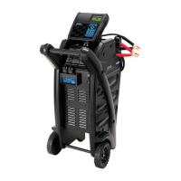
GR8-1200 OEM
Midtronics Inc. 7000 Monroe Street Willowbrook, IL 60527
www.midtronics.com
41
Starter Circuit
The Starter Circuit Test measures the voltage drop of the
starter circuit.
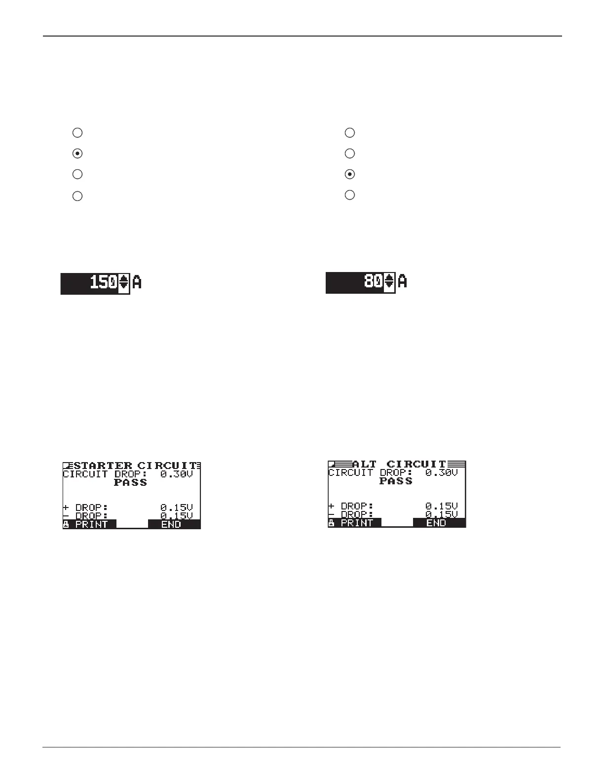
1. SELECT CIRCUIT: Use the UP/DOWN ARROWS or the nu-
merical keypad to select STARTER CIRCUIT.
1
BATTERY GROUND
2 STARTER CIRCUIT
3 ALT CIRCUIT
4 OTHER
Press the NEXT soft key to continue.
2. SET AMPS: Use the UP/DOWN ARROWS or the keypad to
select the rated amperage of the starter circuit. The de-
fault is 150 A.
Press the NEXT soft key to continue.
3. Connect the positive (+) clamp of the battery test leads to
the starter’s battery terminal stud. Connect the negative
(–) clamp to the starter’s housing.
4. Connect the positive (+) DMM clamp to the battery’s posi-
tive (+) post. Connect the negative clamp (–) to the bat-
tery’s (–) negative post.
For the next few seconds the GR8 will display the word TESTING
and a stopwatch while it evaluates the battery ground.
Starter Circuit Test Results
If there is a problem, the decision is CLEAN AND RETEST OR
REPLACE. To print the results, select the PRINT soft key. To
return to the Main Menu, press the END key.
Alternator Circuit
The Alternator Circuit Test measures the voltage drop of the
alternator circuit.
1. SELECT CIRCUIT: Use the UP/DOWN ARROWS or the nu-
merical keypad to select ALT CIRCUIT.
1
BATTERY GROUND
2 STARTER CIRCUIT
3 ALT CIRCUIT
4 OTHER
Press the NEXT soft key to continue.
2. SET AMPS: Use the UP/DOWN ARROWS or the keypad to
select the rated amperage of the alternator circuit. The
default is 80 A.
Press the NEXT soft key to continue.
3. Connect the positive (+) clamp of the battery test leads to
the alternator’s output stud (B+). Connect the negative (–)
clamp to the alternator’s housing.
4. Connect the positive (+) DMM clamp to the battery’s posi-
tive (+) post. Connect the negative clamp (–) to the bat-
tery’s (–) negative post.
For the next few seconds the GR8 will display the word TESTING
and a stopwatch while it evaluates the battery ground.
Alternator Circuit Test Results
If there is a problem, the decision is CLEAN AND RETEST OR
REPLACE. To print the results, select the PRINT soft key. To
return to the Main Menu, press the END key.
Midtronics Inc. 7000 Monroe Street Willowbrook, IL 60527
www.midtronics.com
Chapter 13: Cable Drop Test