Servicing 5-3
board sockets. Carefully pry up the battery retaining lever. Then grasp the battery edges and remove
the device. Set the battery aside.
Note the “+” marking on one side of the replacement battery. When you install a battery, this “+”
marking must face the battery retaining lever. After replacing the battery, set the system clock to the
correct date and time. Also enter the Menu System and check or update system adjustments as
necessary.
•
Coin Counter
Meter replacement requires vault removal. Switch off power to the VGM. Unlock and open the coin
door and cashbox door. Find the meter behind the bottom of the cashbox door. Remove the cashbox.
Remove two mounting screws at the bottom (front) of the vault assembly. Reach through the cash
door. You’ll find two mounting screws at the back of the vault. Remove these. Access the four
remaining vault screws from the inside-back of the cabinet. Remove these four screws. Slide the vault
out of the cabinet.
Locate the meter wires under the vault. Disconnect wiring at the connector. Remove two mounting
screws from the front of the meter. Remove the meter. Assure that the replacement meter has a
diode across its terminals. This diode protects driver circuits from the meter’s inductive kick. Install
the new meter. Log the new meter count.
•
Coin Mechanism
Switch off power to the VGM. Unlock the coin door and swing it open. To clean or replace a coin
mechanism, unlatch and remove it. After reinstallation, assure that the mechanism seats fully in its
bracket. Close and lock the release latch. Then close the door. Enter the Menu System to change the
coin mechanism setup. Test known good and bad coins to verify operation.
•
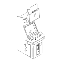
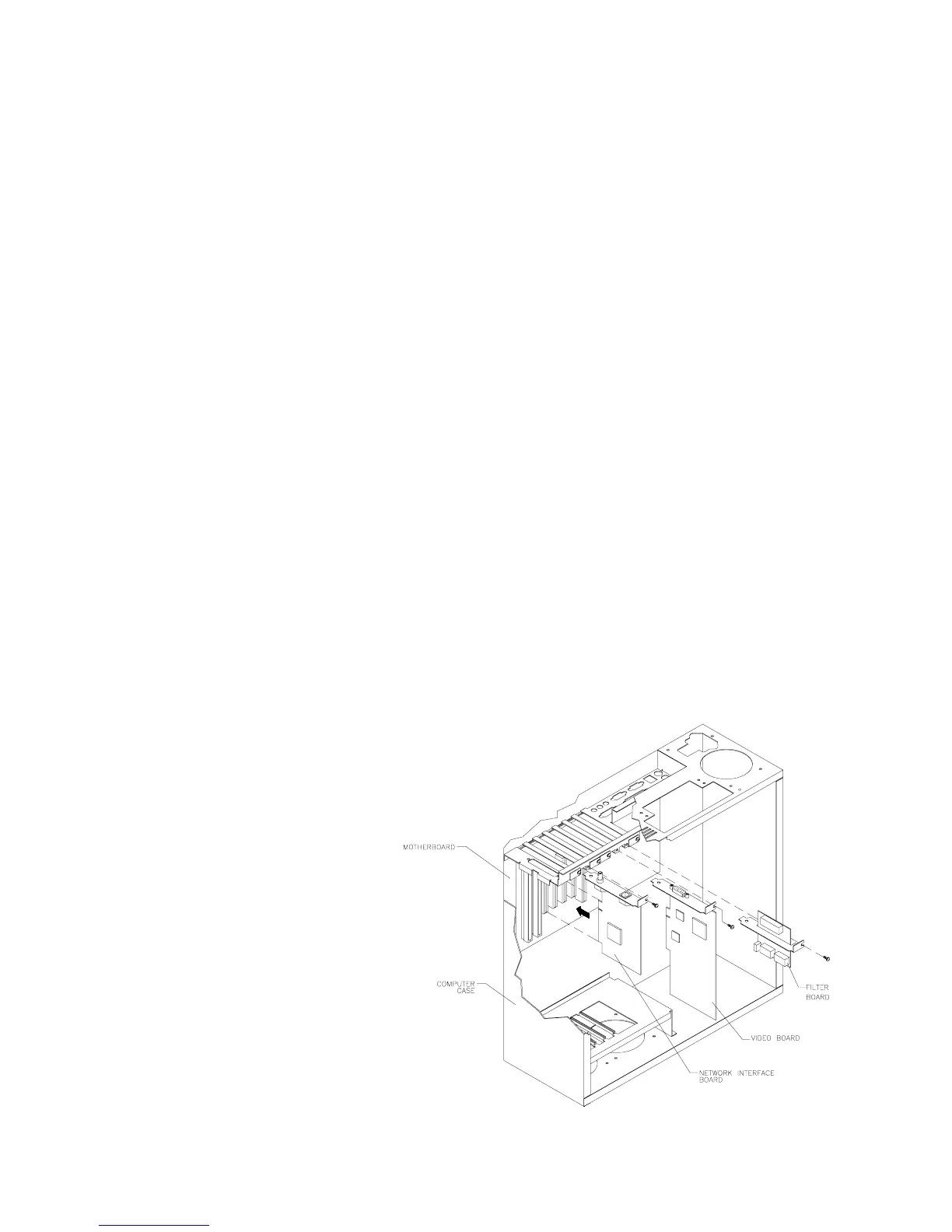
CPU Board
The CPU Board is part of the
Arcade Computer. Switch off
power to the VGM. Open and
remove the rear door. The Arcade
Computer is behind this door. Find
the four metal thumbscrews at the
top and bottom corners of the
computer case. To expose the
CPU Board, loosen, but don’t
remove these screws. Slide off the
back of the computer. Unscrew
and remove the circuit board
retention bars. Disconnect
external cables to the Video
Board, Network Board and Power
Filter Board. Remove the Video
Board, Network Board and Power
Filter Board. Disconnect the floppy
disk power and data cables at the
disk drive. Remove the floppy
drive-mounting bracket. Lift the
bracket and floppy drive out of the
cabinet. Set these aside for
reassembly.