Servicing 5-4
Remove the CPU Board power cables at the CPU Board. Remove the circuit board retention bars.
Disconnect the hard drive power and data cables at the disk drive. Remove CPU Board mounting
screws. Lift the circuit board out of the cabinet. Use anti-static packaging from new parts to store
boards that you won’t reinstall.
•
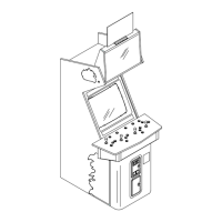
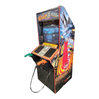
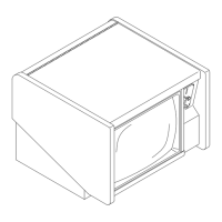
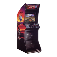
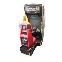
Dashboard and Steering Mechanism
Switch off power to the VGM. Unlock and
remove the rear door. From inside the
cabinet, disconnect the dash cables. Sit in the
driver’s seat and support the steering wheel.
Remove the top two dashboard mounting
screws. Remove the dash bracket. Slide the
viewing glass upward. Lift the glass out of the
cabinet. Remove the bottom two dash
screws. Remove the dashboard and set it on
your workbench.
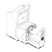
Inspect the motor, pulleys, and belt. If the belt
is broken or shows signs of wear, replace it.
Locate the two nuts on each side of the motor
mounting bracket. Loosen all four bracket
nuts. Rotate the tension adjustment bolt as
necessary. Tighten this bolt until the belt is
taut. Then restore correct tension by
loosening the bolt one full turn. Tighten the
motor bracket nuts.
•
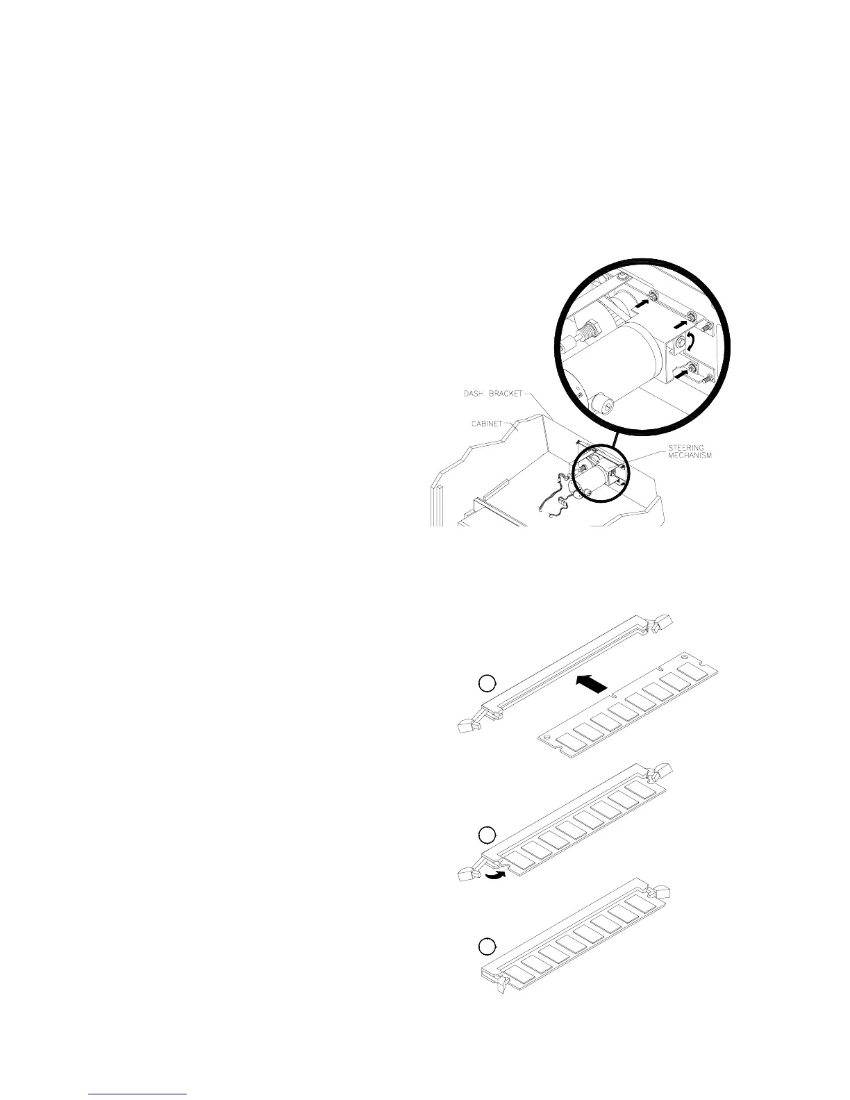
DIMMs (Dual In-Line Memory Modules)
DIMM circuits contain the computer read-write
memory for this VGM. Switch off power to the
VGM. Remove the cabinet rear door. Remove
the back of the Arcade Computer. Unplug the
ribbon cable from the floppy drive. Leave the
other end of the cable attached to the CPU
Board. Unscrew and remove the circuit board
retention bars. Remove the floppy drive
mounting bracket. Remove the floppy drive.
Note DIMM positions. Press out on the locking
retainer on each side of the DIMM. The DIMM
should partially or completely pop out of its
socket. Lift the DIMM from its socket. Handle
the DIMM only by its edges.
To reinstall memory circuits, orient the DIMM
over its socket. Make sure that you’ve
positioned the keying holes and notch properly.
Push the DIMM board into its socket. The
board should snap into place, engaging a
locking retainer at each socket end. Be sure
that the retainers mate tightly with DIMM board
notches. Don’t attempt to force a DIMM into its
socket.
C
B
A