Servicing 5-9
handle it only by its edges. Don’t touch the copper traces! Use anti-static bags and protective
containers to store the board if you won’t reinstall it.
•
Power Supply
CAUTION:
Replace the power supply only with a Midway approved power supply.
Make no substitutions. Otherwise you will void the UL and CE listings on your
video game machine. Non-approved power supplies can pose shock and fire
hazards to players and service personnel.
Switch off power to the VGM. Disconnect the line cord. Unlock and remove the rear door. Remove
the back of the Arcade Computer. Unplug the IEC AC power cord. Inside the Arcade Computer,
disconnect DC power cables. These connect to the hard drive, motherboard and other peripherals.
Remove four mounting screws from the outside of the Arcade Computer enclosure. Lift the power
supply out of the cabinet. Before reinstalling the power supply, check the line voltage switch setting.
•
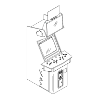
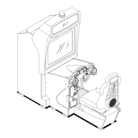
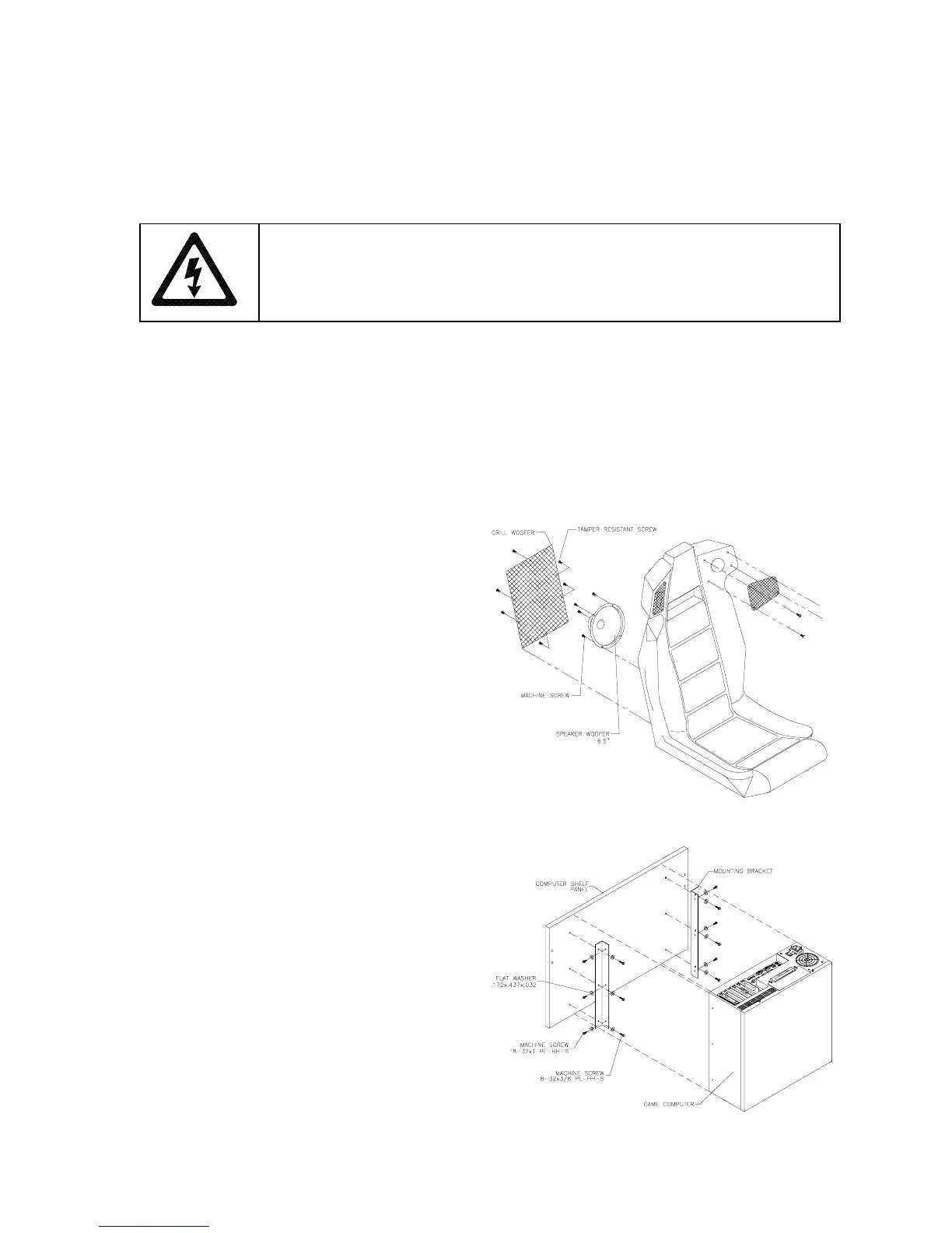
Speakers
This VGM has four speakers. One woofer is
behind a grille at the back of the driver’s seat.
Smaller, full range speakers are behind the
marquee. A second woofer is inside the main
cabinet, accessible from the back. Switch off
power to the VGM.
ACCESSING THE SEAT WOOFER.
Remove
mounting screws and set the speaker grille
aside. Don’t use excess force when removing
or tightening mounting screws threaded into
plastic. Avoid speaker damage by removing
the upper mounting screws first. (Replace
these top screws last.)
ACCESSING THE CABINET WOOFER.
Unlock and remove the rear door. Unscrew
the Arcade Computer mounting brackets.
Disconnect and remove the Arcade Computer.
Unscrew and remove the computer’s wooden
mounting panel. Remove speaker-mounting
screws.
ACCESSING A MARQUEE SPEAKER.
Unscrew and remove the marquee retainer.
Expose the speakers by removing the
marquee glass. Remove speaker-mounting
screws.
SPEAKER REMOVAL.
Assure proper polarity
by marking each speaker wire (“+” or “Gnd”).
Remove the speaker from the enclosure and
disconnect the wire lugs.