-42-
B. DEA 200
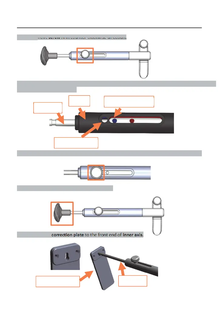
Assembling of Correction Rod
Step 1: Remove screw A in counter-clockwise direction.
Step 2: Rolling the inner axis and the shaft to find out correction rod hole, then align the shaft circle
hole with correction rod hole.
Step 3: Tighten screw A in clockwise direction to correction rod hole (under shaft circle hole).
Step 4: Remove rubber pad of forehead stopper.
Step 5: Assemble correction plate to the front end of inner axis.
screw A
,QQHUD[LV
VKDIWġ
VKDIWFLUFOHKROH
&RUUHFWLRQURGKROH
screw A
rubber pad
FRUUHFWLRQ
ODWH
,QQHUD[LV


 To Next Page